Needle catheter utilizing optical spectroscopy for tumor identification and ablation

a technology of optical spectroscopy and needle catheter, applied in the field of catheters, can solve the problems of steam bubble formation, impedance rise and limit current delivery, not only in tissue heating, but also in electrode heating, etc., and achieve the effect of improving lesions

Pending Publication Date: 2015-06-11
BIOSENSE WEBSTER (ISRAEL) LTD
View PDF12 Cites 9 Cited by
  • Summary
  • Abstract
  • Description
  • Claims
  • Application Information

AI Technical Summary

Benefits of technology

[0012]The present invention addresses the above concerns by providing a catheter that creates enhanced lesions using a needle electrode assembly and employs optical spectroscopy, including transmissive and refractive spectroscopy before, during or after ablation to assess tissue attributes, including malignancy and/or necrosis. The catheter comprises an elongated catheter shaft, a control handle, and a needle electrode assembly that extends through the catheter shaft and the control handle, which can be advanced distally or retracted proximally relative to the catheter shaft for irradiating, penetrating and ablating a target tissue site. The distal end of the needle electrode assembly is adapted to penetrate tissue surface and ablate tissue

Problems solved by technology

Ablation of tissue from an endovascular approach results not only in heating of tissue, but heating of the electrode.
Impedance can then rise and limit current delivery.
Within tissue, overheating can cause steam bubble formation (steam “pops”) with risk of uncontrolled tissue destruction or undesirable perforation of bodily structures.
In cardiac ablation, clinical success is sometimes hampered by inadequate lesion depth and transverse diameter even when using catheters with active cooling of the tip.
Ablation may

Method used


Image

  • Needle catheter utilizing optical spectroscopy for tumor identification and ablation
  • Needle catheter utilizing optical spectroscopy for tumor identification and ablation
  • Needle catheter utilizing optical spectroscopy for tumor identification and ablation

Examples


Embodiment Construction

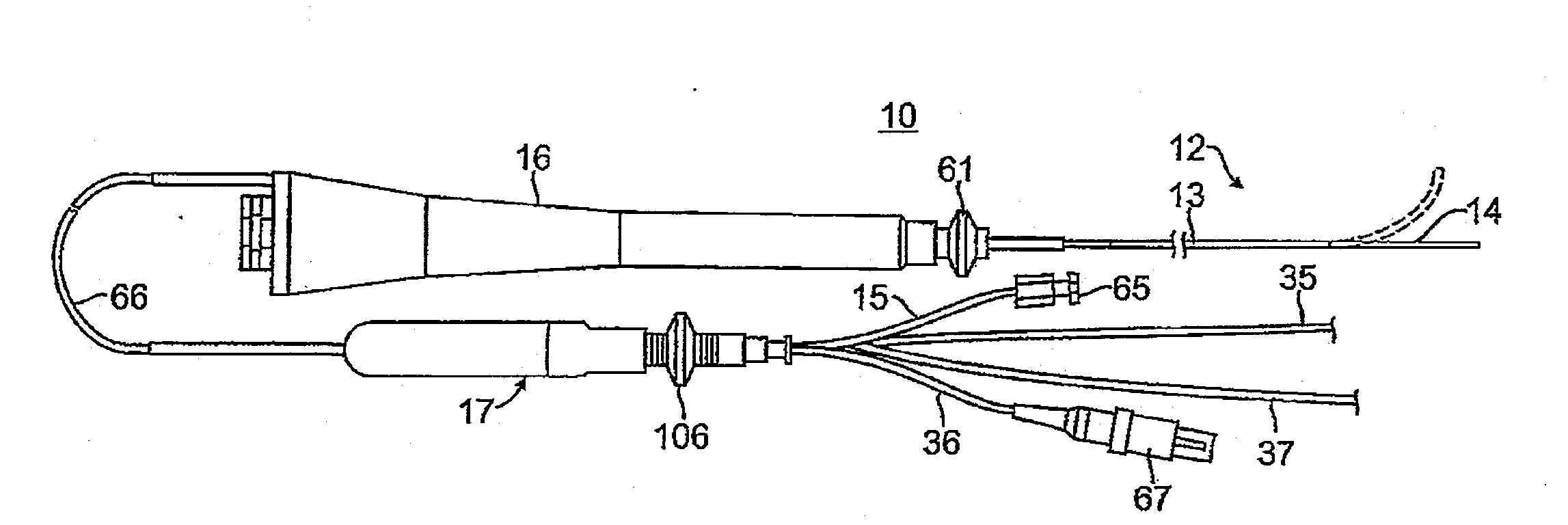
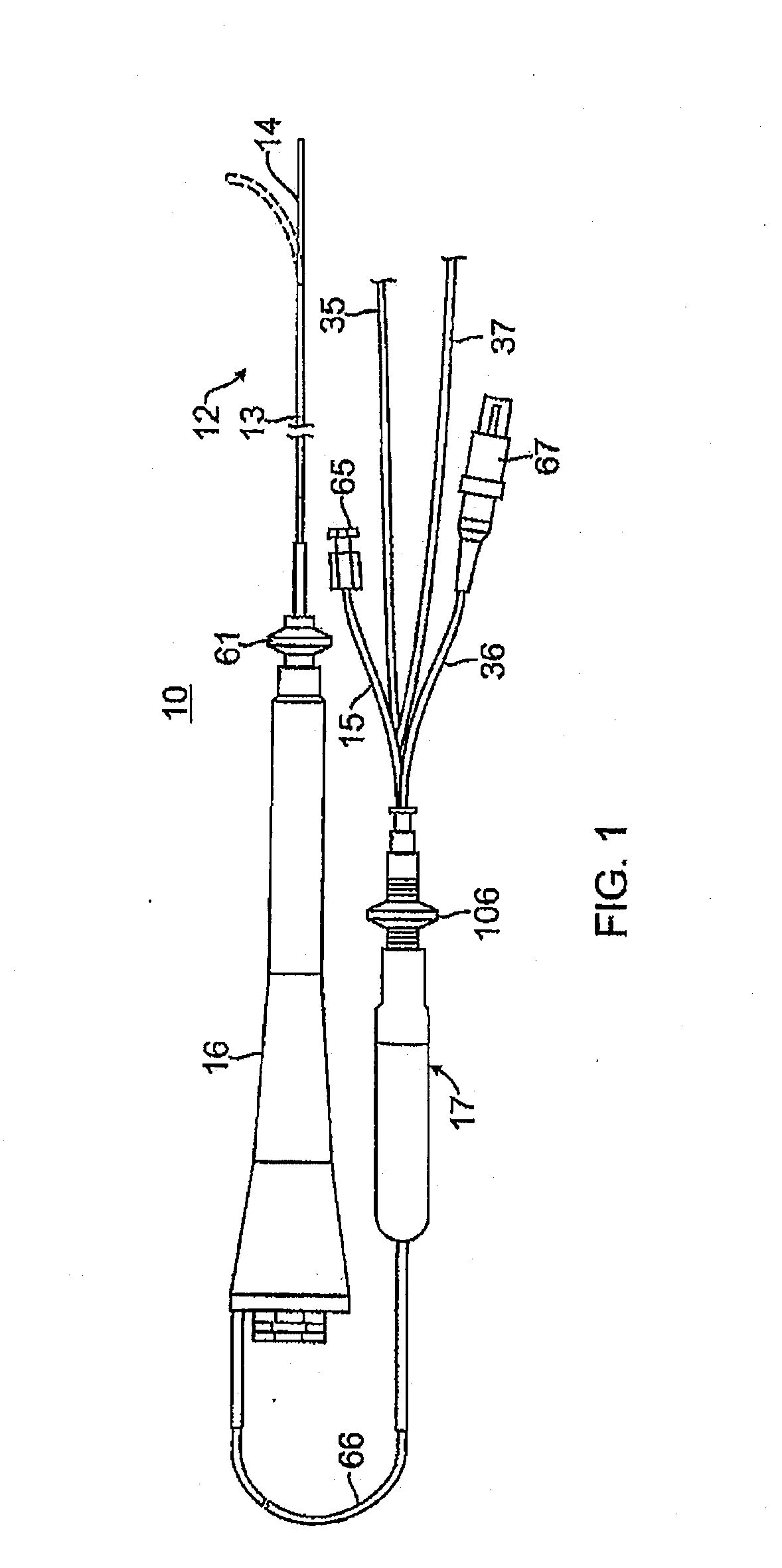
[0046]As shown in FIG. 1, the catheter 10 comprises an elongated catheter body 12 having a proximal shaft 13, a distal shaft 14, a deflection control handle 16 attached to the proximal end of the proximal shaft, and a needle control handle 17 attached indirectly to the catheter body 12 proximal of the deflection control handle 16.

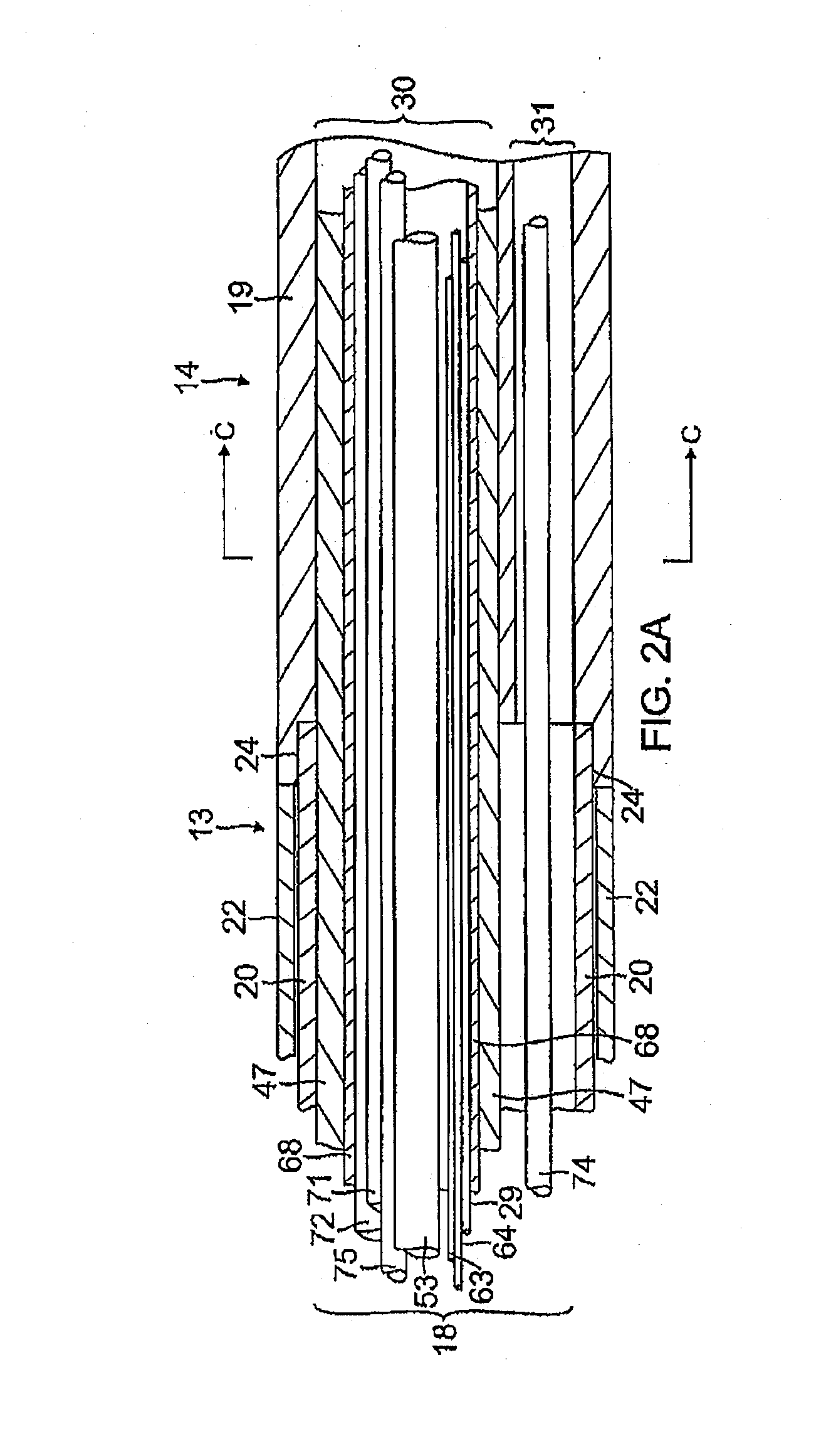
[0047]With reference to FIGS. 2A and 2B, the proximal shaft 13 comprises a single, central or axial lumen 18. The proximal shaft 13 is flexible, i.e., bendable, but substantially non-compressible along its length. The proximal shaft 13 may be of any suitable construction and made of any suitable material. A presently preferred construction comprises an outer wall 22 made of polyurethane or nylon. The outer wall 22 comprises an imbedded braided mesh of stainless steel or the like to increase torsional stiffness of the proximal shaft 13 so that, when the deflection control handle 16 is rotated, the distal shaft 14 of the catheter 10 will rotate in a correspon...


PUM


Abstract

A catheter that creates enhanced lesions uses a needle electrode assembly and employs diffuse reflectance optical spectroscopy, including optical transmissive and refractive spectroscopy before, during or after ablation to assess tissue attributes, including malignancy and/or necrosis. The catheter comprises an elongated catheter body, a control handle, and a longitudinally movable needle electrode assembly and one or more optical wave guides extending from the control handle and through the catheter body, wherein the needle electrode assembly is adapted for penetrating and ablating tissue at a distal end of the catheter and at least one optical waveguide is adapted to collect light refracted from the tissue at or near the distal end of the catheter. An integrated ablation and spectroscopy system of the present invention comprises an RF generator, a light source and a light analyzer adapted to analyze the light collected by the at least one waveguide.

Description

FIELD OF INVENTION[0001]This invention relates to catheters, in particular, pulmonary catheters for ablation and tissue diagnostics.BACKGROUND[0002]Radiofrequency (RF) ablation of cardiac and other tissue is a well-known method for creating thermal injury lesions at the tip of an electrode. Radiofrequency current is delivered between a skin (ground) patch and the electrode. Electrical resistance at the electrode-tissue interface results in direct resistive heating of a small area, the size of which depends upon the size of the electrode, electrode tissue contact, and current (density). Further tissue heating results from conduction of heat within the tissue to a larger zone. Tissue heated beyond a threshold of approximately 50-55 degrees C. is irreversibly injured (ablated).[0003]Resistive heating is caused by energy absorption due to electrical resistance. Energy absorption is related to the square of current density and inversely with tissue conductivity. Current density varies wi...

Claims


Application Information

Patent Timeline
IPC IPC(8): A61B18/20
CPCA61B2018/2065A61B18/20A61B5/0075A61B18/1492A61B2017/00061A61B2018/00029A61B2018/00351A61B2018/00541A61B2018/00839A61B2018/00904A61B2018/1425A61B5/0084
Inventor BEECKLER, CHRISTOPHER
Owner BIOSENSE WEBSTER (ISRAEL) LTD
Why Eureka
Try Eureka