Eureka AIR delivers breakthrough ideas for toughest innovation challenges, trusted by R&D personnel around the world.

Light-assisted acoustic cleaning tool

a technology of acoustic cleaning and acoustic technology, which is applied in the direction of carpet cleaners, cleaning using liquids, lighting and heating apparatus, etc., can solve the problems of difficult to remove sub-100 nanometer (nm) particles from surfaces, waste that is environmentally harmful, and high process costs, so as to facilitate the generation of acoustic waves and facilitate the removal of particles

Inactive Publication Date: 2015-06-11
SEMATECH
View PDF0 Cites 15 Cited by
  • Summary
  • Abstract
  • Description
  • Claims
  • Application Information

AI Technical Summary

Benefits of technology

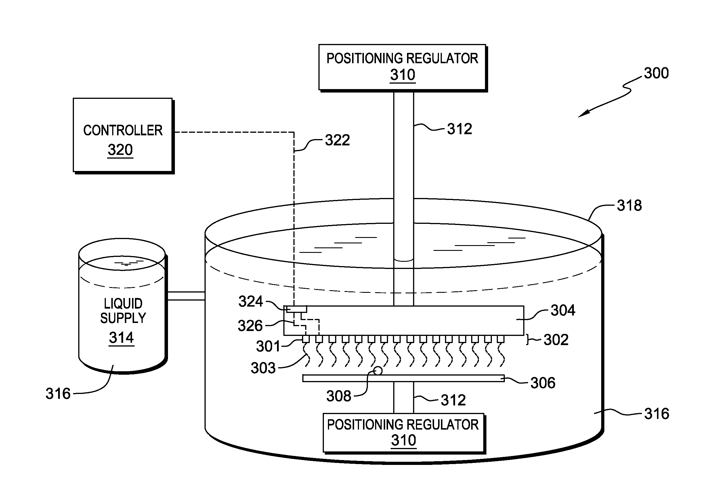
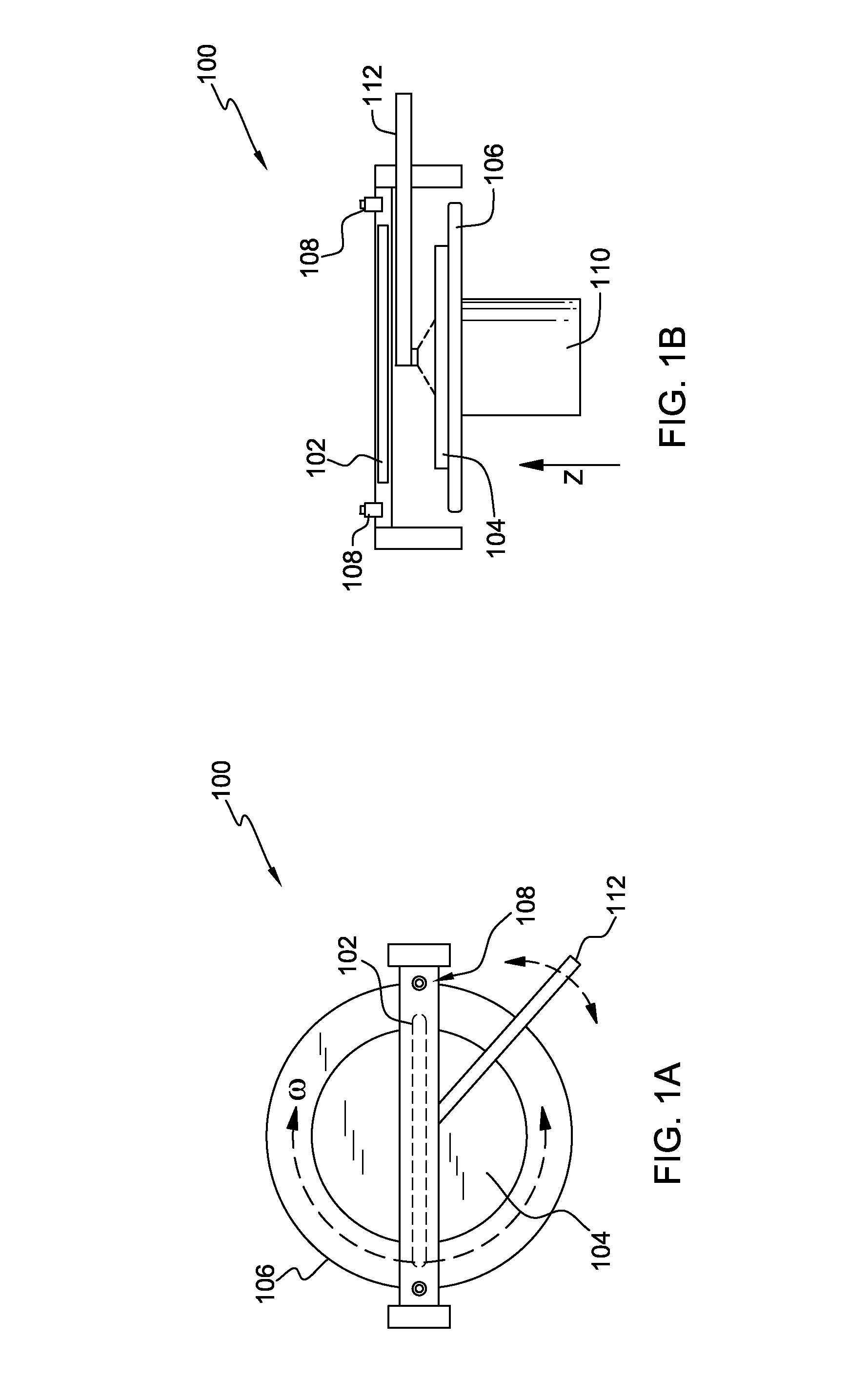
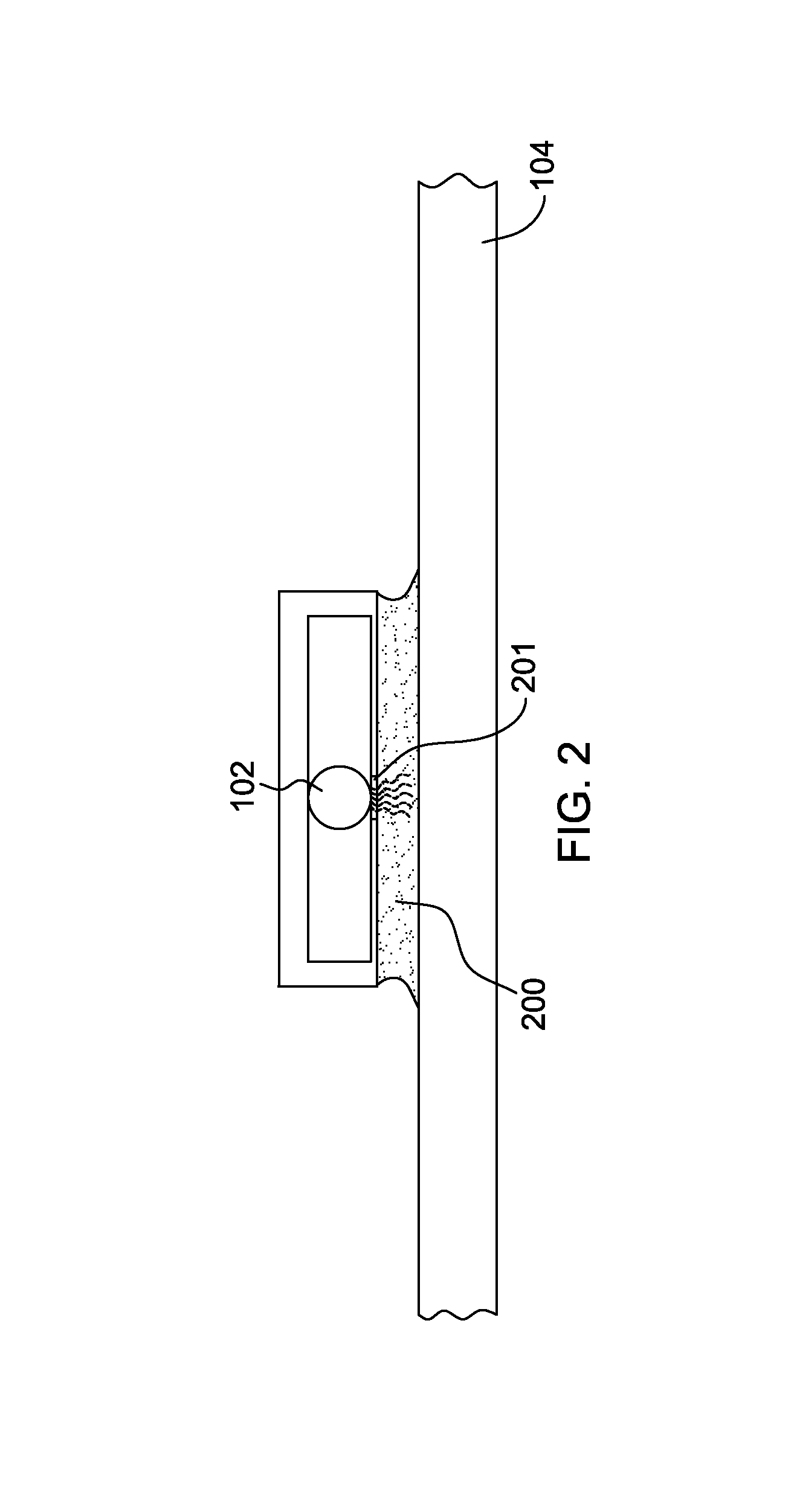
This patent describes an apparatus and method for cleaning surfaces by using an acoustic wave generator and a light source to remove particles. The apparatus includes an acoustic wave generator with an acoustic transducer and an acoustic coupler substrate that directs acoustic waves towards the surface. A light source is also coupled to the acoustic coupler substrate, which directs light towards the surface. The acoustic waves and light from the generators are directed towards the surface simultaneously, creating an effective removal of particles. The technical effect of this invention is the development of a tool that can effectively remove particles from surfaces using an acoustic wave generator and light source.

Problems solved by technology

Removal of sub-100 nanometer (nm) particles from a surface can be a challenging subject for semiconductor fabrication processes.
Generally, the particles may accumulate when the substrate is being stored or is in a stand-by state between successive processes, and the accumulated particles may cause defects, particularly for integrated circuits on a substrate.
However, these processes are both expensive and produce waste that is environmentally harmful.
Additionally, the use of a spin brush can be effective in removing large particles, but is not particularly effective in removing particles on the order of sub-microns or smaller.
Additionally, Next Generation Lithography (NGL) used in semiconductor technology includes reflective optics on glass substrates which have a surface roughness of approximately 1.5 Angstrom RMS or less to prevent scattering of the light, which may degrade the lithography process performance.
Conventional wet cleaning techniques that use under etching of particles to remove particles from a surface are not applicable in this situation since they increase the surface roughness beyond the required value.
In addition, many advanced cleaning tools do not have the ability to totally remove particles with these dimensions, from the surface of a plate.
This is due to the lack of a mechanism to convey a relatively high energy or momentum to the particles in the vicinity (few nanometers) of the surface.
Additionally, current tools typically lack a mechanism to increase the population of reactive species in the vicinity of the liquid-surface interface.

Method used


Image

  • Light-assisted acoustic cleaning tool
  • Light-assisted acoustic cleaning tool
  • Light-assisted acoustic cleaning tool

Examples


Embodiment Construction

[0030]Aspects of the present invention and certain features, advantages, and details thereof, are explained more fully below with reference to the non-limiting examples illustrated in the accompanying drawings. Descriptions of well-known materials, fabrication tools, processing techniques, etc, are omitted so as not to unnecessarily obscure the invention in detail. It should be understood, however, that the detailed description and the specific examples, while indicating aspects of the invention, are given by way of illustration only, and are not by way of limitation. Various substitutions, modifications, additions, and / or arrangements, within the spirit and / or scope of the underlying inventive concepts will be apparent to those skilled in the art from this disclosure. Note also that reference is made below to the drawings, which are not drawn to scale to facilitate an understanding of the invention, wherein the same or similar reference numbers used throughout different figures des...


PUM


Abstract

A cleaning tool facilitating removal of particles from a surface is provided which includes an acoustic wave generator and one or more light-emitting diodes. The acoustic wave generator, which is configured to direct acoustic waves towards the surface to be cleaned, may include an acoustic transducer that facilitates generating the acoustic waves, and an acoustic coupler substrate through which the acoustic waves propagate. The light-emitting diode(s), which is configured to direct light towards the surface to be cleaned, is coupled to the acoustic coupler substrate of the acoustic wave generator. The acoustic wave generator and the light-emitting diode(s) are spaced from the surface to be cleaned, and are configured to selectively concurrently direct overlapping, at least partially, acoustic waves and light energy towards the surface to facilitate removal of particles by breaking bonds between the particles and the surface.

Description

BACKGROUND[0001]This invention relates generally to semiconductor fabrication processes, and more particularly, to apparatuses and methods for facilitating removal of particles from surfaces, such as from a surface of a reticle, mask, mask blank, wafer, substrate, glass plate, flat panel, etc.[0002]Removal of sub-100 nanometer (nm) particles from a surface can be a challenging subject for semiconductor fabrication processes. These particles may include contaminants on the surface including materials such as organic material, dust, residue, and metal impurities. Generally, the particles may accumulate when the substrate is being stored or is in a stand-by state between successive processes, and the accumulated particles may cause defects, particularly for integrated circuits on a substrate.[0003]The surface-particle interactions depend on the material and the surface structure. As such, the energy transfer efficiency needed to remove a particle from a surface strongly depends on the ...

Claims


Application Information

Patent Timeline
Patent Type & Authority Applications(United States)
IPC IPC(8): B08B7/02B08B7/04B08B3/12B08B7/00
CPCB08B7/026B08B3/12B08B7/04B08B7/0035H01L21/67057H01L21/67115
Inventor RASTEGAR, ABBAS
Owner SEMATECH
Why Eureka
Eureka Blog
Learn More