In order to release this copper, the furnace can be tilted on the floor bearings, which means that the vertical portion 206 must be made shorter, thus significantly decreasing the intended
energy performance.
2.—For batch-type charging and melting furnaces, the most important ones are:
a.—
Reverberatory furnace, originally designed in the 50s by Maerz, according to U.S. Pat. No. 2,864,602, schematically represented in FIG. 5 in a more recent version. This furnace is able to melt copper scrap with a content of at least 92%. This furnace can be tilted, preferably through a system of wheels or rollers 501 and hydraulic cylinders 502, to facilitate the processes of emptying and deslagging. The charging door 503 is situated on one of the sides, making it hard to insert copper scrap since the charge must be distributed inside the furnace so as to keep it from accumulating in the vicinity of the door. The opening time is high, with a great amount of energy lost as a result. Likewise, it is very difficult to collect the
combustion gases that exit through the charging door.
b.—
Turret furnace, according to
patent application WO2012038140, schematically represented in FIG. 6. This furnace is also of the tilting reverberatory type, and is characterized by having, in the central part of the vault, a
turret that protrudes and has an arched ceiling 601 delimited by the charging door of the furnace 602. The aim of this solution is to increase furnace capacity and facilitate the charging process. The main drawback of this furnace is its low energy efficiency, since opening the charging door brings about the
stack effect, with a resulting loss of heat. At this point it is worth mentioning that the previously-described
turret-charging furnaces, i.e. the shaft, Cosmelt and
hearth-shaft varieties, also have said
stack effect, and channel the gases through the material to be melted and towards the exit stack, which is not so in the case of the
turret furnace.
c.—Elliptical furnace, according to patent ES2271898, schematically represented in FIG. 4. This furnace has an elliptical or oval-shaped transverse cross-section, and can rotate around its rotation axis by an angle of more than 40°, typically 90°. The proper melting position (FIG. 4) is when the surface of the bath 401 is greater than its depth 402h. The proper refining and mixing position is when the surface of the bath is less than its depth. The limitation of this furnace is its small capacity of between 20 and 50 mt. The fact that it is charged from the side has the same drawbacks as those described for the furnace in FIG. 5.
d.—Cylindrical furnace, also known as a drum furnace, according to U.S. Pat. No. 4,245,821, represented schematically in FIG. 7. Usually the melting process takes place in another furnace, and the drum furnace is used to refine the molten copper. When used for melting, it has problems in terms of both charging and heat loss. In order to generate a proper exchange between the additive and the
liquid copper, given the great difference in their density, bath surfaces 701 must be large, avoiding bath depths 702h greater than 700 mm. Cylindrical-type furnaces hinder this exchange, as they are furnaces with large depths of
liquid copper.
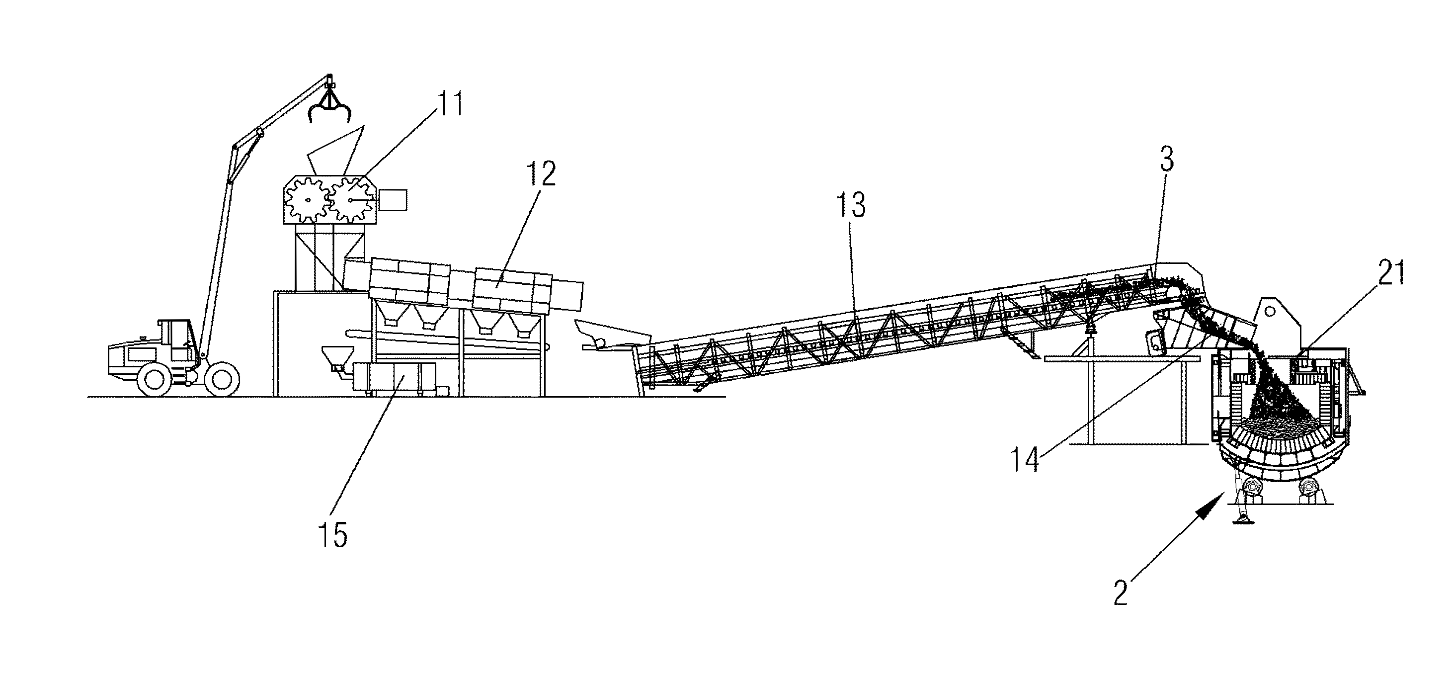
Given that the amount charged is limited by the capacity of the loaders, trucks or skips, the furnace door must be opened several times for the furnace to be completely charged, with the loss of energy that this entails.
Moreover, with these charging systems it is not possible to optimize the space taken up by the scrap, which are not homogeneous in shape and size, and require the size of the opening of the charging door of the furnace to have dimensions large enough to receive the
loader, or the wagon
truck, or the skip.
1.—Loss of energy efficiency due to non-
metal materials that accompany copper scrap, as copper scrap are accompanied by non-
metal impurities that cause loss of energy, as these materials must be melted if they are charged into the furnace.
2.—Loss of energy efficiency due to the fact that the non-
metal materials mentioned in section 1 are heat insulators, and so once the copper has melted these lighter materials float on the surface of the liquid
molten metal, leading to poor
heat transmission.
3.—These non-metal materials charged into the furnace cause a significant increase in
slag.
4.—Loss of energy efficiency in a
reverberatory furnace, due to the fact that the commercial forms of copper scrap do not allow for proper heat exchange between the burner flames and the charge, leading to low melting performance.
5.—Decrease the number of times the charging door of the furnace is opened, in order to obtain very
high energy performance as compared to the methods known in the state of the art.
6.—Minimize the necessary section of the charging door, in order to obtain very
high energy performance as compared to the methods known in the state of the art.
This is not so in the case of so-called secondary emissions; because they are emissions brought about by opening up the furnace, and very specifically by opening the charging door, these gases are difficult to channel due to the large quantity of gas that is released.
We must also bear in mind that during the process of charging copper scrap, when the latter come into contact with the
atmosphere of the hot furnace, they generate a high volume of
combustion gases due to the nature of the charge, since, as has been mentioned, copper and
metal impurities are accompanied by a large amount of non-metal material that combusts and becomes volatile, and highly
pollutant.

