
Ion trap mass spectrometer using cold electron souce

a mass spectrometer and electron source technology, applied in the direction of electron/ion optical arrangement, particle separator tube details, separation process, etc., can solve the problems of rapid consumption of battery power in a portable mass spectrometer, and difficulty in controlling the device using the filament, so as to achieve accurate adjustment

Active Publication Date: 2015-06-11
KOREA BASIC SCI INST
View PDF1 Cites 12 Cited by
  • Summary
  • Abstract
  • Description
  • Claims
  • Application Information

AI Technical Summary

Benefits of technology

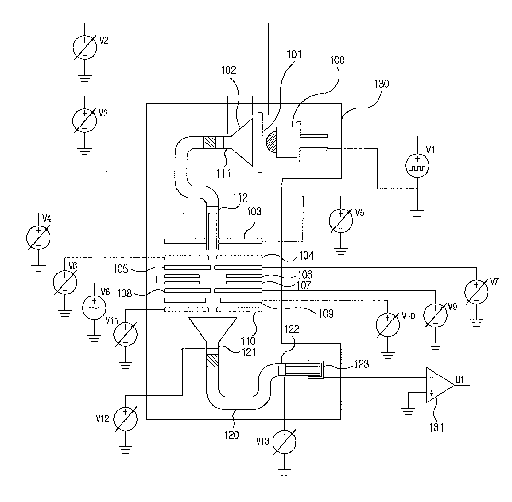
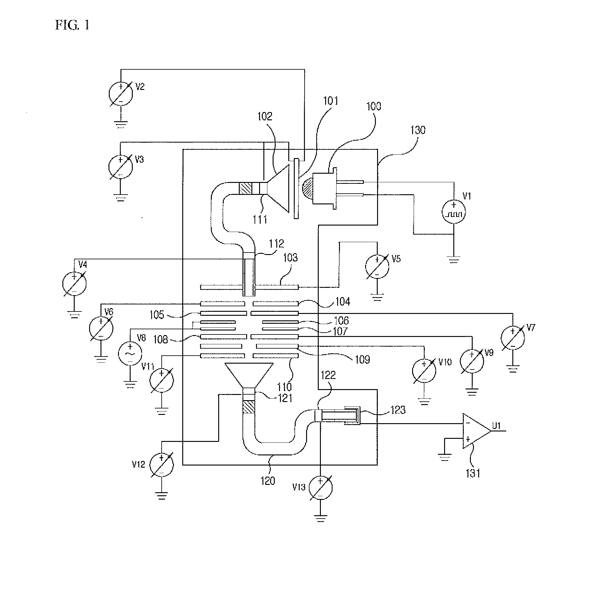
The present invention provides a mass spectrometer using a cold electron source, which uses a microchannel plate and an electron multiplier to amplify electron beams and improve the ionization rate. The electron beams are first induced by ultraviolet photons emitted from an ultraviolet diode, and then amplified using a channeltron electron multiplier. The amplified electron beams are then accurately adjusted and injected into an ion trap, where the ions are trapped and detected based on their mass spectrum. The mass spectrometer includes an ionization source, a microchannel plate, a channeltron electron multiplier, an electron focusing lens, an ion trap mass separator, an ion filter, and an ion detector. The technical effect is to increase the amplification rate of electron beams and improve the ionization rate of gaseous molecules for accurate mass spectrometry analysis.

Problems solved by technology

However, due to high power consumption, battery power is rapidly consumed in a portable mass spectrometer.
Further, a reaction of electron emission caused by a high temperature increase is slow, and thus the device using the filament is difficult to control in a mass spectrometer which is suitable to produce a continuous output electron beam and requires pulse ionization within a short time.

Method used


Image

  • Ion trap mass spectrometer using cold electron souce
  • Ion trap mass spectrometer using cold electron souce
  • Ion trap mass spectrometer using cold electron souce

Examples


Embodiment Construction

[0017]Exemplary embodiments of the present invention will be described in detail below with reference to the accompanying drawings. While the present invention is shown and described in connection with exemplary embodiments thereof, it will be apparent to those skilled in the art that various modifications can be made without departing from the spirit and scope of the invention.

[0018]An ion trap mass spectrometer using a cold electron source according to an embodiment of the present invention will be described in conjunction with the accompanying drawings as follow.

[0019]FIG. 1 is a configuration diagram of ion trap mass spectrometer using a cold electron source according to an embodiment of the present invention, including an ultraviolet diode 100 which emits ultraviolet rays by supplying a power source, an MCP module 101 whose back plate obtains electron beams in quantity by inducing initial electron emission of ultraviolet photons from the ultraviolet diode 100 and amplifying the...


PUM


Abstract

The present invention relates to an ion trap mass spectrometer using a cold electron source, in a production of a portable mass spectrometer, in which a microchannel plate (MCP) module is used, initial electrons are induced by injecting ultraviolet photons emitted from an ultraviolet diode to a front surface of the MCP module, electron beams amplified from the electrons are amplified using a channeltron electron multiplier (CEM), the amplified electron beams are accurately adjusted and injected into an ion trap, thus increasing the amplification rate, and since a quadrupole field is used as an ion filter which returns the initially injected electrons to the inside of an ion trap mass separator, the ionization rate increases.

Description

CROSS-REFERENCE TO RELATED APPLICATION[0001]This application claims priority to and the benefit of Korean Patent Application No. 2013-0150883, filed on Dec. 5, 2013, the disclosure of which is incorporated herein by reference in its entirety.BACKGROUND[0002]1. Field of the Invention[0003]The present invention relates to an ion trap mass spectrometer, and more particularly, to an ion trap mass spectrometer using a cold electron source, in which cold electrons are produced at room temperature using an ultraviolet light emitting diode (UV LED), a microchannel plate (MCP) electron multiplier plate, and a channeltron electron multiplier (CEM), without using a thermionic source using a filament, and are applied to the mass spectrometer.[0004]2. Discussion of Related Art[0005]Generally, in a mass spectrometer, a process of ionizing gaseous molecules is required first to separate molecular ions according to masses of molecular ions and analyze components.[0006]A method of ionizing gaseous m...

Claims


Application Information

Patent Timeline
IPC IPC(8): H01J49/14H01J49/04H01J49/06
CPCH01J49/147H01J49/0422H01J49/06H01J27/205H01J49/08H01J49/26
Inventor KIM, SEUNG YONGYANG, MOKIM, HYUNSIK
Owner KOREA BASIC SCI INST
Learn More