Multi functional sensor system for gas turbine combustion monitoring and control

a sensor system and gas turbine technology, applied in the field of multi-functional sensor systems for gas turbine combustion monitoring and control, can solve the problems of controller changing the operating condition of the engine, destroying the components of the combustion engine, and affecting the performance of the engine, so as to optimize the engine control and performance.

Active Publication Date: 2015-06-18
SIEMENS ENERGY INC
View PDF2 Cites 30 Cited by
  • Summary
  • Abstract
  • Description
  • Claims
  • Application Information

AI Technical Summary

Benefits of technology

[0024]Embodiments of this monitoring and control system with multi-function sensors operate by evaluating dynamic pressure sensor data for combustion anomalies while also monitoring accurate combustion gas temperature continuously in real time. Once the monitoring and control system detects that there is a fault anomaly it evaluates the fault in conjunction with the monitored combustor gas temperature to classify or determine the type of fault. This system classifies various types of developing combustion anomalies, with the ability to predict flame on, flame out, flashback. The system embodiments als

Problems solved by technology

Thus, flame flashback and/or other combustion anomalies may cause undesirable damage and possibly even destruction of combustion engine components, such that repair or replacement of such components may become necessary.
For example, a controller may monitor a measured turbine exhaust temperature, and a measured change in temperature at the exhaust may result in the controller changing an operating condition of the engine.
Thus, different adverse conditions related to combustion currently require separate sensor designs and/or

Method used


Image

  • Multi functional sensor system for gas turbine combustion monitoring and control
  • Multi functional sensor system for gas turbine combustion monitoring and control
  • Multi functional sensor system for gas turbine combustion monitoring and control

Examples


Embodiment Construction

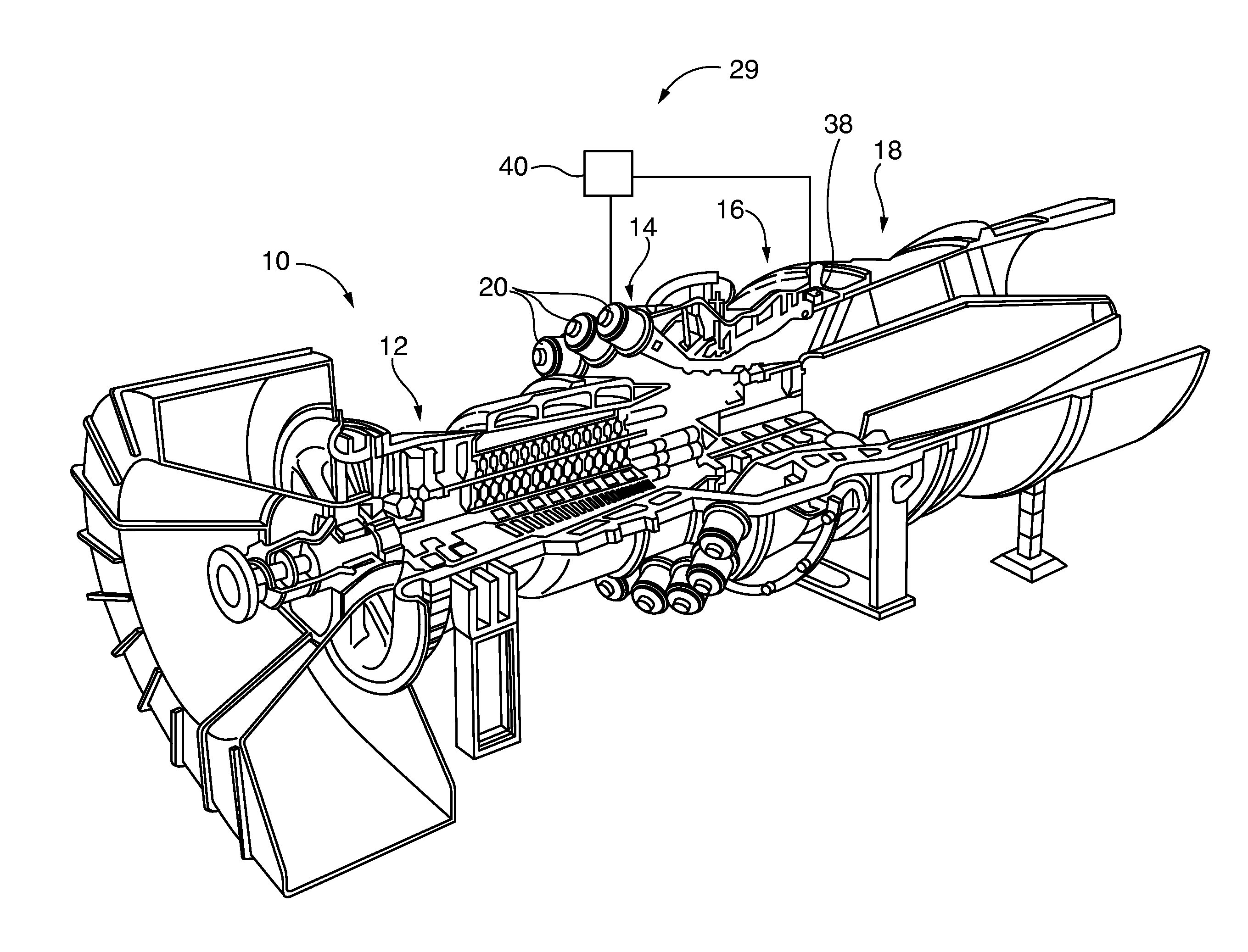
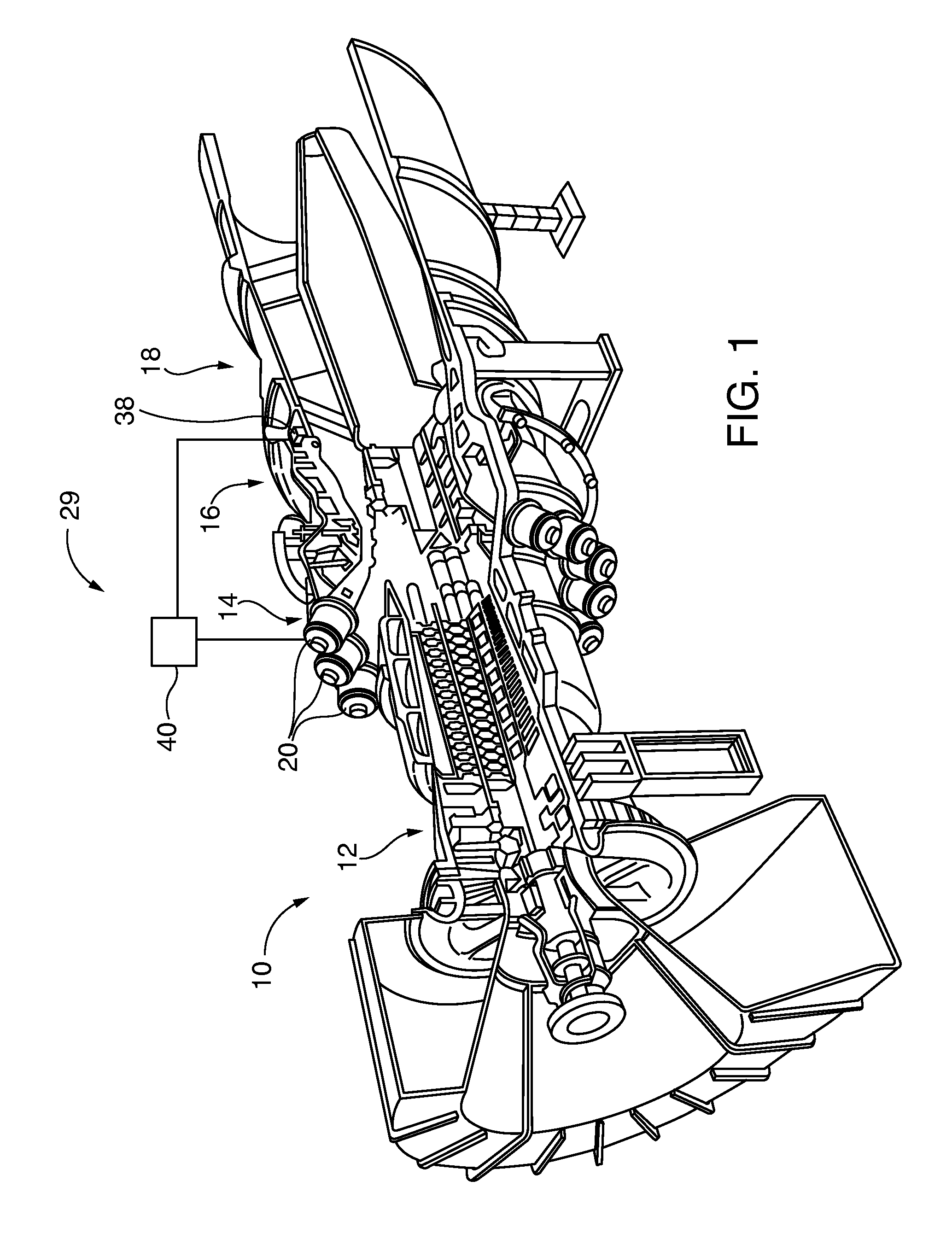
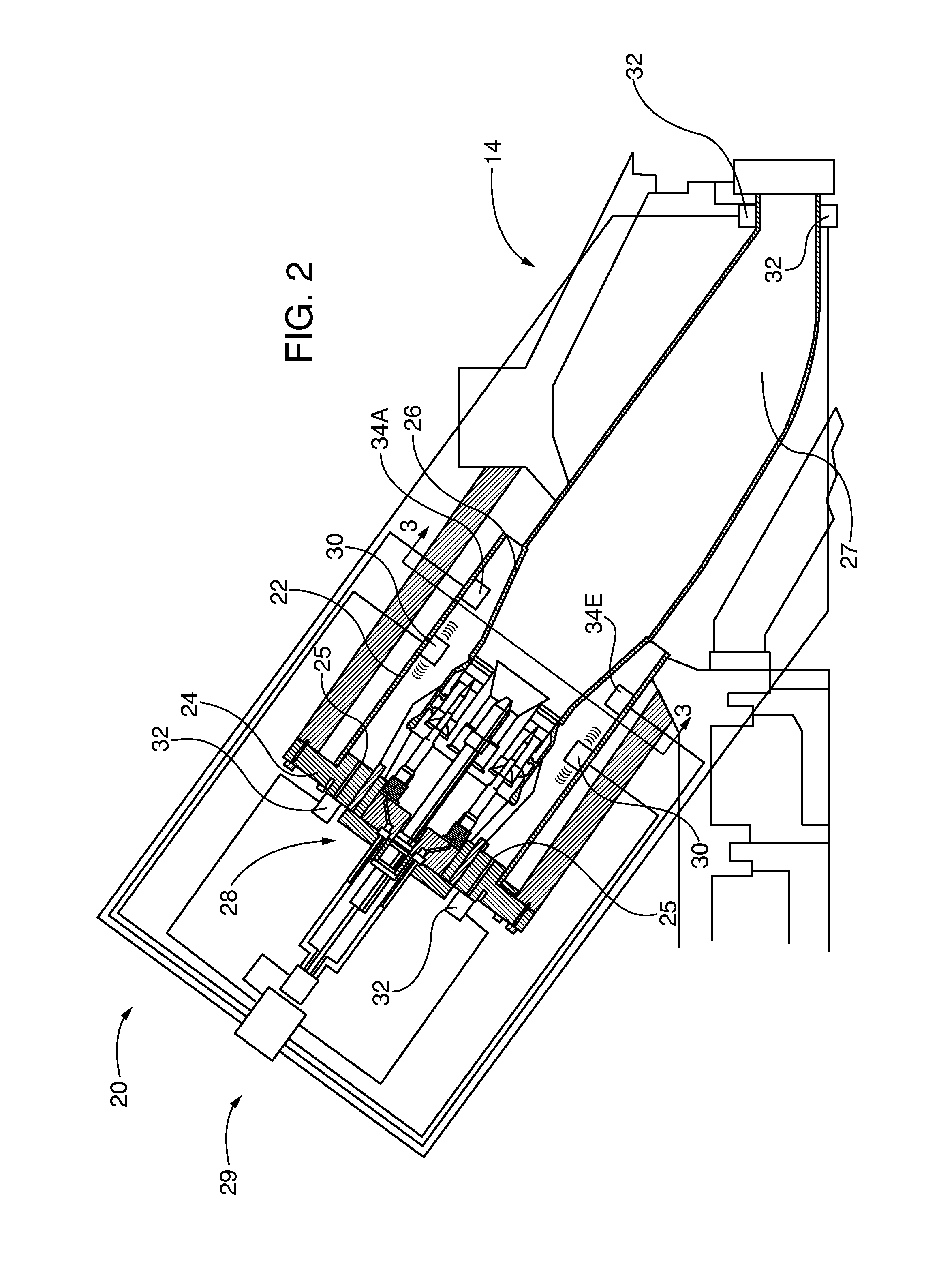
[0036]After considering the following description, those skilled in the art will clearly realize that the teachings of the present invention can be readily utilized in a combustion monitoring and control system that can identify and classify combustion anomalies, and also actively control the gas turbine combustion process within the engine combustors. Some embodiments of the methods and system incorporate one or more thermoacoustic dynamic pressure sensors that are selectively oriented or arrayed in the combustor. The thermoacoustic sensors measure vibratory responses of the combustor that are generated within the combustion process. Sensor outputs are utilized in the monitoring and control system controller to identify anomalies using wavelet or Fourier analysis techniques. In some embodiments bulk temperature is also monitored using dominant mode acoustic frequency analysis techniques.

[0037]In some embodiments, acoustic pyrometry-based active temperature monitoring is incorporate...


PUM


Abstract

Thermoacoustic sensors, such as dynamic pressure sensors, in the combustor measure vibratory responses of the combustor. An integrated monitoring and control system controller correlates sensor readings with combustion thermoacoustic properties in order to identify combustion anomalies by wavelet or Fourier analysis techniques; determine bulk temperature characteristics within the combustor with dominant mode frequency analysis techniques; and optionally determines absolute active path temperatures within the combustor with acoustic pyrometry transmission and time-of-flight analysis techniques. In some embodiments all of the monitoring functions are performed with a commonly shared array of thermoacoustic sensors that function as both combustion dynamics thermoacoustic vibration/wave receivers and acoustic transmitters. The monitored combustion properties are used for controlling gas turbine combustion.

Description

CROSS-REFERENCE TO RELATED APPLICATIONS[0001]This application incorporates by reference the following co-pending United States utility patent applications in their entirety as if fully set forth herein:[0002]“Active Temperature Monitoring In Gas Turbine Combustors” filed concurrently on the same date, Serial Number unknown, file 2013P22724US (Siemens 230);[0003]“Gas Turbine Engine Control Using Acoustic Pyrometry”, filed on Dec. 14, 2010, Ser. No. 12 / 967,148, Publication No. US2012 / 0150413; and[0004]“Temperature Measurement in a Gas Turbine Engine Combustor”, filed on Mar. 14, 2013, Ser. No. 13 / 804,132.[0005]This application also incorporates by reference in its entirety as if fully set forth herein U.S. Pat. No. 7,853,433, “Combustion Anomaly Detection Via Wavelet Analysis of Dynamic Sensor Signals”, issued Dec. 14, 2010.BACKGROUND OF THE INVENTION[0006]1. Field of the Invention[0007]The invention relates to combustion monitoring and control, including anomaly detection and classif...

Claims


Application Information

Patent Timeline
IPC IPC(8): G01K11/22G01K11/24G01M15/14
CPCG01K11/22G01K11/24G01M15/14F23N5/10F23N5/16F23N2223/00F23N2225/08F23N2241/20F23R3/44F02C7/00F02C9/00F23R3/00Y02T50/60
Inventor DESILVA, UPUL P.
Owner SIEMENS ENERGY INC
Why Eureka
Try Eureka