Driver assistance system comprising an optical detector with active scene illumination

a technology of optical detector and driver assistance, which is applied in the direction of distance measurement, instruments, and using reradiation, etc., can solve the problems of reducing the life of the device, reducing the efficiency of electrical-to-optical power conversion of typical devices, and reducing the available space for integrating the illumination uni

a technology of optical detector and driver assistance, which is applied in the direction of distance measurement, instruments, and using reradiation, etc., can solve the problems of reducing the life of the device, reducing the efficiency of electrical-to-optical power conversion of typical devices, and reducing the available space for integrating the illumination uni

US20150168555A1Active Publication Date: 2015-06-18IEE INT ELECTRONICS & ENG SA

Image

  • Driver assistance system comprising an optical detector with active scene illumination
  • Driver assistance system comprising an optical detector with active scene illumination
  • Driver assistance system comprising an optical detector with active scene illumination

Examples


Embodiment Construction

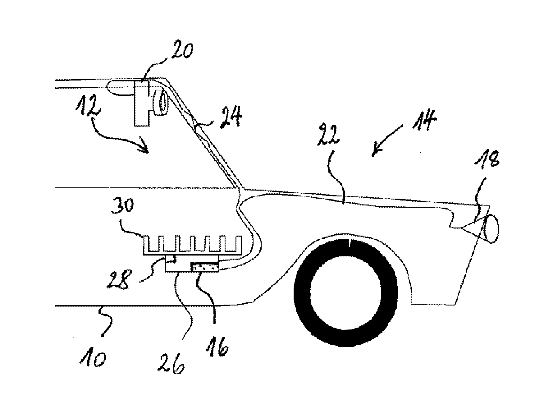
[0024]Most modern ADAS employ optical detection systems, which require an active illumination in the infrared wavelength range. The data of several detection systems, three-dimensional and / or two-dimensional, is evaluated to obtain a greater accuracy and reliability required for safety functions like automatic emergency braking. Three-dimensional imagers, which use the time-of-flight method require an active illumination which is amplitude-modulated or pulsed in the HF frequency range. For these systems, it is typical that the illumination module is built in a single unit, which comprises the light source, its driver and a dedicated optical system to transform the output of the light source device into the light field distribution required in the scene. Similarly, sensor systems using the structured-light imaging method employ illumination units, which include light source, driver electronics and projection optics.

[0025]Since the electrical-to-optical power conversion efficiency of ...


PUM


Abstract

A driver assistance system (12) comprises an optical detector (14) with active scene illumination. The optical detector includes at least one of a stereoscopic imager, a time-of-flight imager, a structured-light imager and a night vision system. The optical detector includes a light source (16) for converting electrical energy into light, projection optics (18) for illuminating a scene with light generated by the light source and one or more optical sensors (20) for detecting light returned from the scene in response to the scene being illuminated. The light source is thermally connected to a heat sink (30) for evacuating heat produced by the light source and the projection optics are optically connected to the light source with one or more optical fibers (22) for transport of light generated by the light source to the projection optics.

Description

TECHNICAL FIELD[0001]The present invention generally relates to a driver assistance system comprising an optical detector with active scene illumination.BACKGROUND ART[0002]In Advanced Driver Assistance Systems (ADAS), active illumination systems, preferably of infrared wavelength, are useful to realize several functions ranging from Night Vision to different methods of three-dimensional optical sensing like time-of-flight techniques using a pulsed or periodically modulated active illumination or different techniques based on the triangulation method, for example structured-light imaging or stereo-vision at night.[0003]In order to achieve large illumination angles, the optical unit projecting the illumination field should be installed either in the headlamp or radiator cowling region, in the front of the car excluding more re-entrant locations, or, alternatively, in the top-middle area of the windshield or the windshield corners.[0004]However, for the mitigation of injuries to pedes...

Claims


Application Information

Patent Timeline
18 Jun 2015
Publication
US20150168555A1
IPC
G01S17/89; G01S17/93; G01S7/481; G01S17/48; G01S17/931
CPC
G01S17/89; G01S7/4818; G01S17/936; G01S17/48; G01S17/931; B60Q1/0011
Inventors
HERSCHBACH, NORBERT