Apparatus and method of transferring, focusing and purging of powder for direct printing at low temperature

a technology of direct printing and focusing, applied in the field of apparatus and methods for transferring, focusing and purging powder for direct printing at low temperature, can solve the problems of difficult to increase the pressure difference, difficult to produce a print, and the rare cases where direct printing is used to print a precise pattern on a substrate are still rare, so as to achieve the effect of further enhancing the focusing

Active Publication Date: 2015-06-25
SEOUL NAT UNIV R&DB FOUND
View PDF0 Cites 3 Cited by
  • Summary
  • Abstract
  • Description
  • Claims
  • Application Information

AI Technical Summary

Benefits of technology

[0034]Accordingly, the present invention has been made keeping in mind the above problems occurring in the prior art, and an object of the present invention is to provide apparatus and method for transferring, focusing and purging powder for direct printing at low temperature which can precisely and directly print a desired pattern on a desired portion of a substrate even at low temperature in such a way that solid powder or particles are accelerated by transfer gas.
[0035]Another object of the present invention is to provide apparatus and method for transferring, focusing and purging powder for direct printing at low temperature in which when particles are deposited on a base material or substrate by accelerating the particles using transfer gas, the amount and timing that the particles, in detail, the particles dispersed in the transfer gas, that is, the aerosolized particles, are supplied onto the substrate can be effectively controlled, whereby a precise pattern can be reliably formed on the substrate without using an additional tool such as a mask.
[0036]A further object of the present invention is to provide apparatus and method for transferring, focusing and purging powder for direct printing at low temperature in which a required amount of aerosolized powder supplied and discharged from a high pressure side to a low pressure side at high speed is minimized, the timing at which the aerosolized powder is supplied to the substrate is precisely controlled, and these printing operations are repeatedly conducted by steps, whereby a pattern can be precisely printed.
[0037]In order to accomplish the above object, the present invention provides an apparatus for transferring, focusing and purging powder for direct printing at low temperature in which a high pressure side and a low pressure side are separated from each other by an on-off means (on-off valve or the like), and decompression of the low pressure side is induced by repeating momentary opening and closing of the on-off means so that a pressure difference between the high pressure side and the low pressure side can be further increased to enhance the ability to accelerate particles, and which is configured such that the on-off timing of the valve is controlled in consideration of particle acceleration dynamic characteristics depending on transfer gas, whereby the supply of aerosolized powder, the injection quantity thereof and the supply timing can be precisely controlled.
[0039]As proposed in the prior art documents, in a transfer gas supply method in which an on-off means between a high pressure side and a low pressure side is repeatedly opened and closed by a pulse control method, acceleration characteristics of transfer gas and particles can be obtained to some degree. However, the prior art documents are focused on only effective deposition of particles through repetition of the opening and closing of the of-off means. On the other hand, in the present invention, as well as using the pulse control opening and closing method, the supply of aerosolized powder, the injection quantity thereof and the supply timing can be controlled. Thereby, a pattern can be precisely printed on a substrate without using a separated mask.
[0040]Furthermore, particles can be discharged from a nozzle by transfer gas in a focused form by selecting an appropriate shape of an injection nozzle. It could be configured from a test that when aerosolized powder is applied from the nozzle to the substrate by a momentary pulse control method, such focusing effect can be further enhanced.

Problems solved by technology

However, the printing technology using ink is disadvantageous in that additional heat treatment is required because liquefied ink is used, it is difficult to produce a print result structure having a high aspect ratio, and it must depend on a wet process.
However, cases where these techniques are used to directly print a precise pattern on a substrate are still rare.
The reason for this is because it is difficult to use transfer gas to form uniformly-dispersed particles from powder, that is, aerosolized powder in transfer gas, aeromechanically control a flow rate of aerosolized powder and a transfer timing of aerosolized powder, and accelerate particles at high speed and precisely deposit them on a portion of a substrate.
However, these conventional methods are problematic in that since transfer gas is continuously supplied only at a constant flow rate, it is difficult to increase a pressure difference, to a certain level, between a transfer gas supply side of high pressure and the substrate maintained at low pressure.
However, although these modified conventional techniques can be easily used for large area deposition and coating, research and development on reducing the size of a deposition pattern and controlling the shape of the pattern and the position of deposition have not been sufficient.
In the conventional methods in which particles are accelerated by transfer gas and deposited on a substrate and in the modified conventional methods, critical problems in printing a precise pattern (mircroscale) on a substrate are that the amount of aerosolized powder supplied or sprayed onto the substrate for deposition is large, and research and development of a technique of controlling it has not been sufficient.
However, with regard to the modified methods in which particles are deposited on a substrate in such a way as to accelerate them using transfer gas, research and development on a technique of supplying, by steps, the minimum amount aerosolized powder necessary to manufacture a precise pattern and controlling the size of the deposition pattern have been unsatisfactory.

Method used


Image

  • Apparatus and method of transferring, focusing and purging of powder for direct printing at low temperature
  • Apparatus and method of transferring, focusing and purging of powder for direct printing at low temperature
  • Apparatus and method of transferring, focusing and purging of powder for direct printing at low temperature

Examples


Embodiment Construction

[0055]Hereinafter, preferred embodiments of the present invention will be described in detail with reference to the attached drawings.

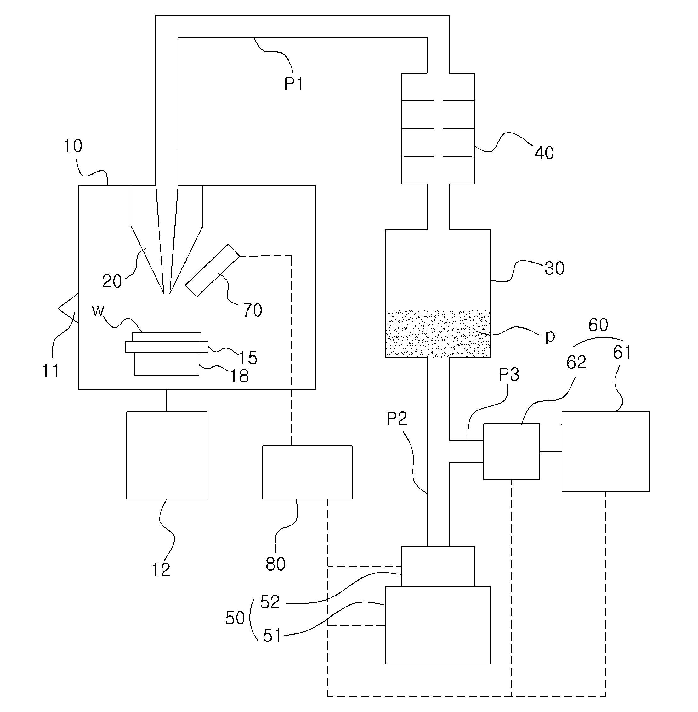
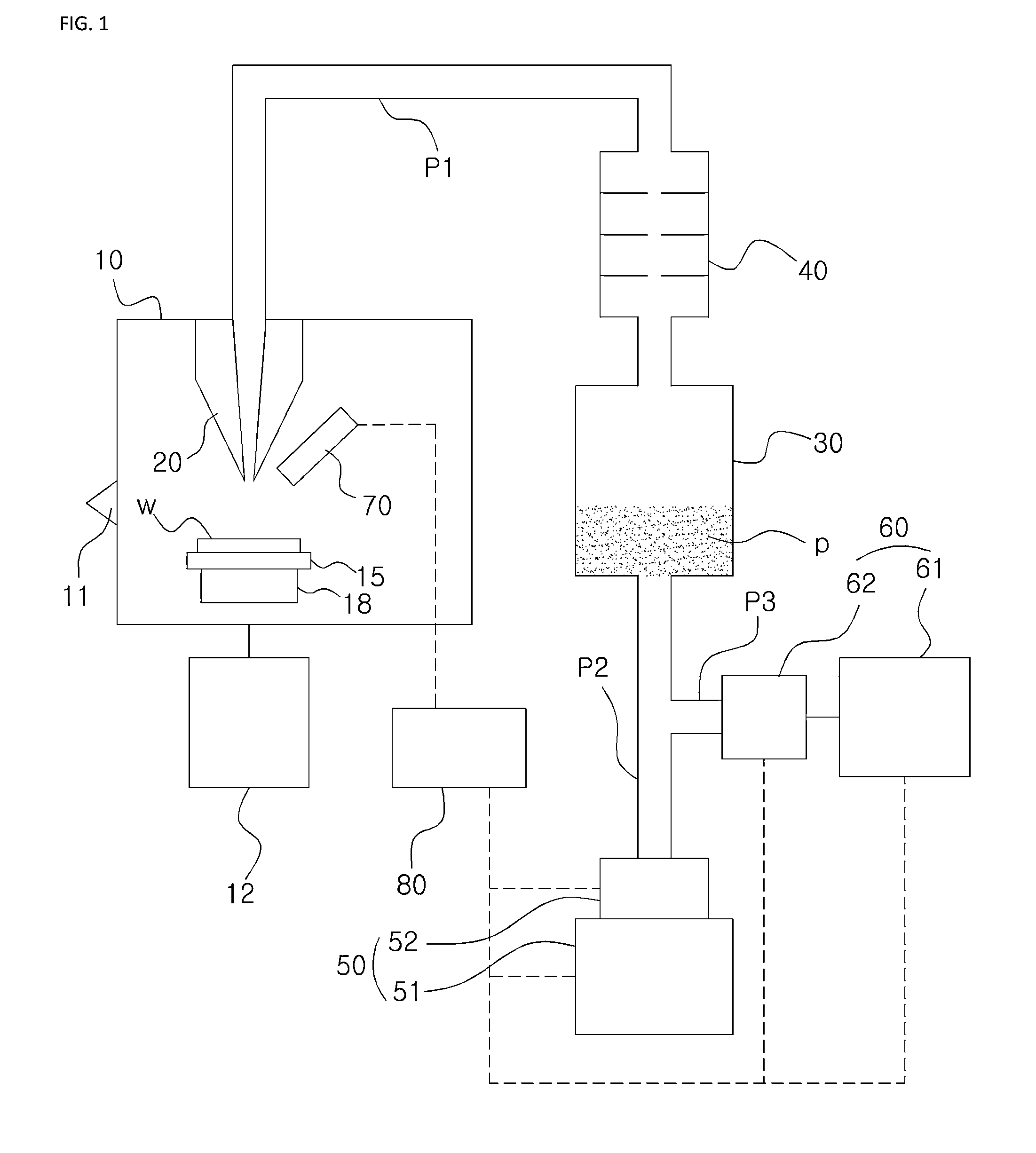
[0056]FIG. 1 is a schematic view illustrating the construction of an apparatus for transferring, focusing and purging powder for direct printing at low temperature, according to a preferred embodiment of the present invention.

[0057]For reference, in FIG. 1, reference numeral 11 denotes a vacuum gauge.

[0058]As shown in FIG. 1, the apparatus according to the present invention includes an operation chamber housing 10, an injection nozzle 20, a reservoir tank 30, a filter 40, a pressure unit 50 and a purging unit 60.

[0059]The operation chamber housing 10 defines therein a space for receiving a work target w and creates a vacuum environment, in detail, maintains the internal space in a predetermined negative pressure state (e.g., ranging from 10−2 torr to 10−6 torr).

[0060]For example, the work target w may be a substrate, in more detail, a PCB (printed cir...


PUM


Abstract

Disclosed herein are apparatus and method for transferring, focusing and purging powder for direct printing at low temperature. A filter is provided between an operation chamber housing in which a work target is disposed and a reservoir tank which contains powder to adjust the amount of particles transferred from the reservoir tank into the operation chamber housing. A pressure unit connected to the reservoir tank generates air pressure for applying powder to the work target. A purging unit connected to the reservoir tank generates pressure for returning powder that has remained in the operation chamber housing, the filter, etc. to the reservoir tank after work has been completed. The apparatus is configured such that a series of process of transferring powder to be applied to the surface of the work target and returning remnant powder to the reservoir tank can be rapidly and smoothly conducted.

Description

BACKGROUND OF THE INVENTION[0001]1. Field of the Invention[0002]The present invention relates generally to apparatuses and methods for transferring, focusing and purging powder for direct printing at low temperature and, more particularly, to an apparatus and method for transferring, focusing and purging powder for direct printing at low temperature which are configured to rapidly and smoothly conduct a series of processes for directly printing metal or ceramic powder on a substrate in a variety of patterns at a micro scale at low temperature without conducting additional heat treatment: aerosolizing powder through a momentary pulse type valve control, discharging a desired amount of powder through a nozzle, directly applying the powder to the surface of a work target such as a substrate in a focused form to print a desired pattern, stabilizing powder after discharge of the desired amount of powder has completed, and then returning the powder.[0003]2. Description of the Related Art[...

Claims


Application Information

Patent Timeline
Patent Type & Authority Applications(United States)
IPC IPC(8): B41J2/175
CPCB41J2/17596B41J2/17563B41J2/175C23C24/04
Inventor AHN, SUNG-HOONLEE, GIL-YONG
Owner SEOUL NAT UNIV R&DB FOUND
Why Eureka
Try Eureka