

Electrical circuit to impedance match a source and a load at multiple frequencies, method to design such a circuit
- Summary
- Abstract
- Description
- Claims
- Application Information
AI Technical Summary
Benefits of technology
Problems solved by technology
Method used
Image

Examples
Embodiment Construction
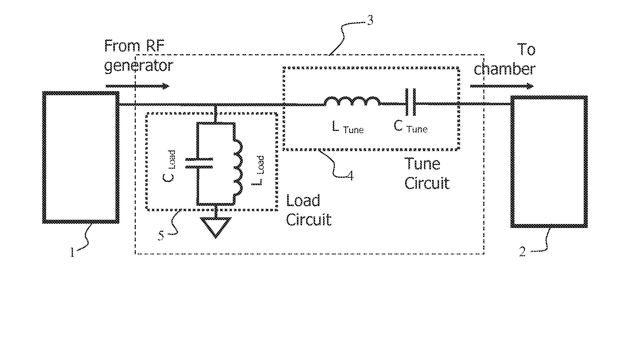
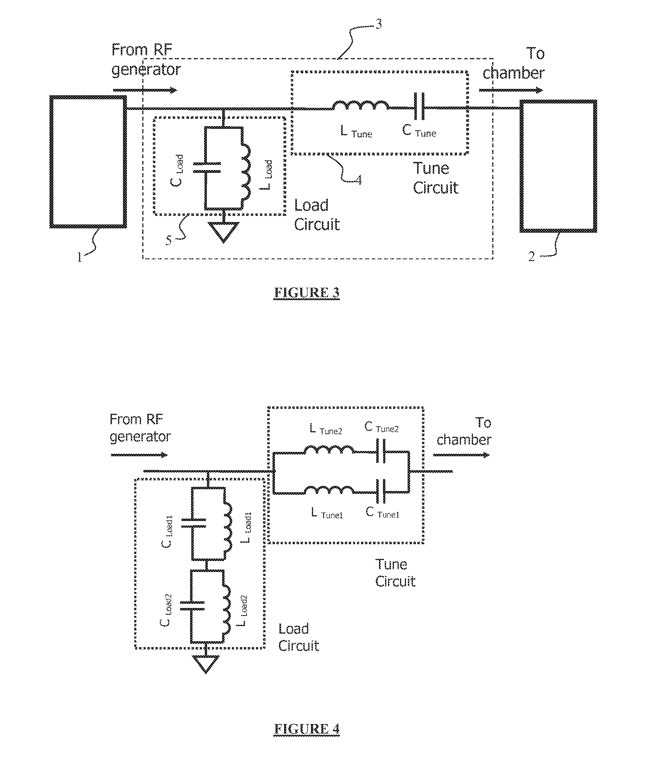
[0054]Reference is now made to the drawing figures, in which like numerals or terms refer to like elements throughout the several views.
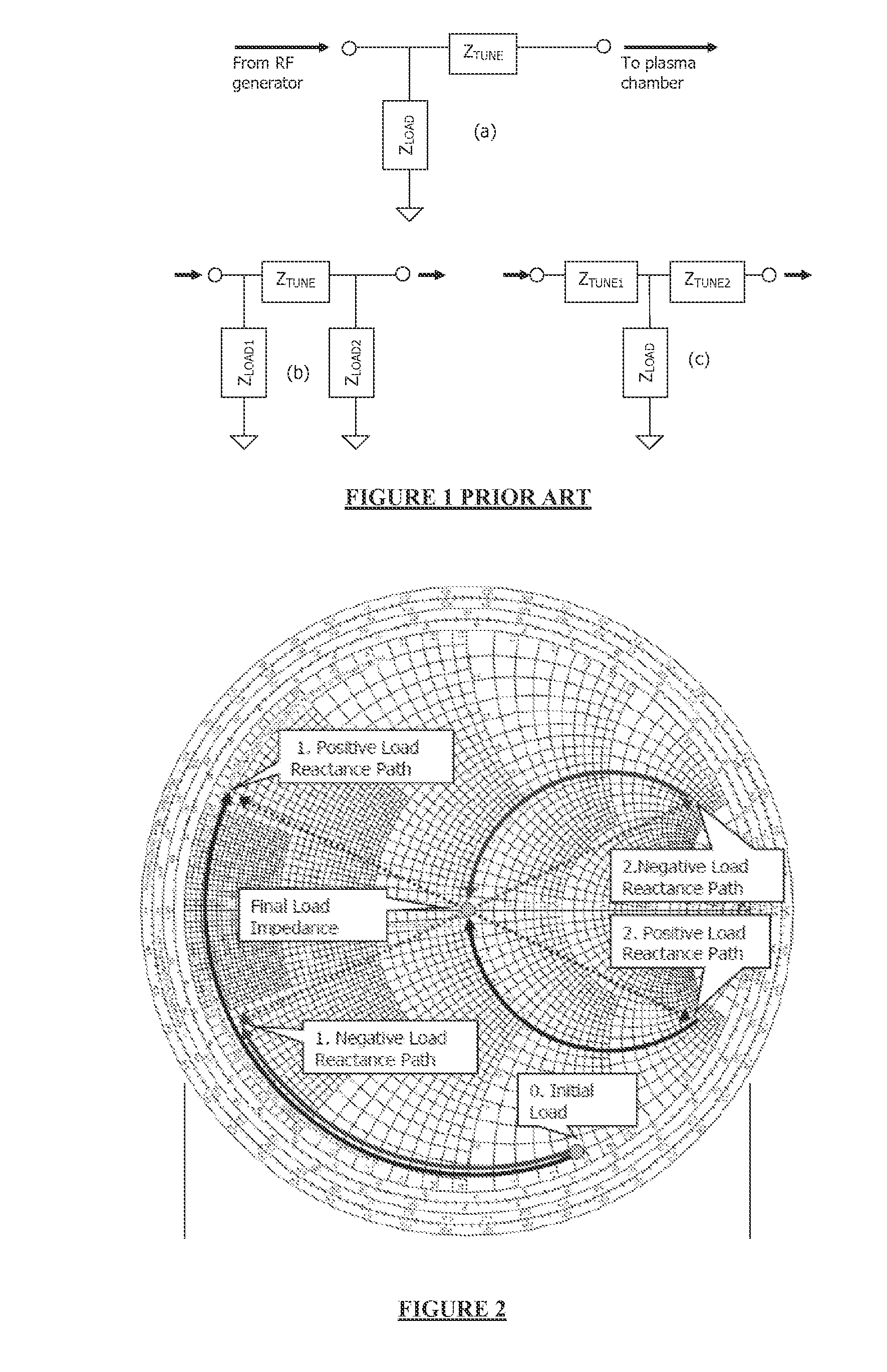
[0055]The Smith chart is a nomogram showing the value of the real part and the imaginary part of impedance. The graph thus consists of a network of a circle or arc.
[0056]The Smith chart is used to assist in solving problems with transmission lines and matching circuits. It can be used to represent many parameters including impedances, admittances, reflection coefficients, scattering parameters, noise figure circles, constant gain contours and regions for unconditional stability, including mechanical vibrations analysis. The Smith chart is plotted on the complex reflection coefficient plane in two dimensions and is scaled in normalised impedance (the most common), normalised admittance or both, using different colours to distinguish between them. The most commonly used normalization impedance is 50 ohms which is arranged on the horizontal line and il...
PUM
| Property | Measurement | Unit |
|---|---|---|
| Frequency | aaaaa | aaaaa |
| Electric impedance | aaaaa | aaaaa |
Abstract
Description
Claims
Application Information