Welding method and apparatus therefor

a welding electrode and soldering technology, applied in the field of methods, can solve the problems of reducing the product life of the cap to a great extent, welding electrodes may not achieve the full potential life extension, and defects found in esd coatings, so as to improve the welding structure and performan

Active Publication Date: 2015-07-02
HUYS IND
View PDF0 Cites 8 Cited by
  • Summary
  • Abstract
  • Description
  • Claims
  • Application Information

AI Technical Summary

Benefits of technology

[0016]In the view of the inventors herein, ultrasonic vibration may help to improve welding structure and performance in the welding and casting industries. Ultrasonic cavitation and acoustic streaming effects of ultrasonic vibration that may aid in refining grains in the heat affects zones of castings and weld pools. Chinese patent CN102019531A, which pertains to a portable ultrasonic assisted electro-spark deposition integrated repair and polish device and technology, suggests an ultrasonic approach. However, the ultrasonic excitation is added to modulation of the discharge electrode. This ultrasonic vibration applies only to the coating transfer of the deposition material. It appears to have little effect on the coating layer on the base metal of the workpiece.

Problems solved by technology

However, there are some defects found in ESD coatings.
Consequently, welding electrodes may not achieve the full potential life extension because of the flaws in the heat affect zone of the substrate matrix.
These defects may tend to reduce the product life of the caps to a great extent.
The life of welding electrodes has become an important issue in the resistance welding of galvanized steel and aluminum sheets.
This in turn increases the consumption in automotive production and thus raises the production cost.
Due to thermal shock when the spark discharges, ESD coatings may tend to have flaws. FIG. 5 herein shows typical coating defeats (delaminations, porosity, cracks and uneven coating) of a welding electrode after the application of TiC coating using the ESD process.
As a result, a friction stir process may not be suitable for the modification of surface coatings, such as those on resistance spot welding electrodes.
In addition, the process is difficult, and power consumption may be high.

Method used


Image

  • Welding method and apparatus therefor
  • Welding method and apparatus therefor
  • Welding method and apparatus therefor

Examples


Embodiment Construction

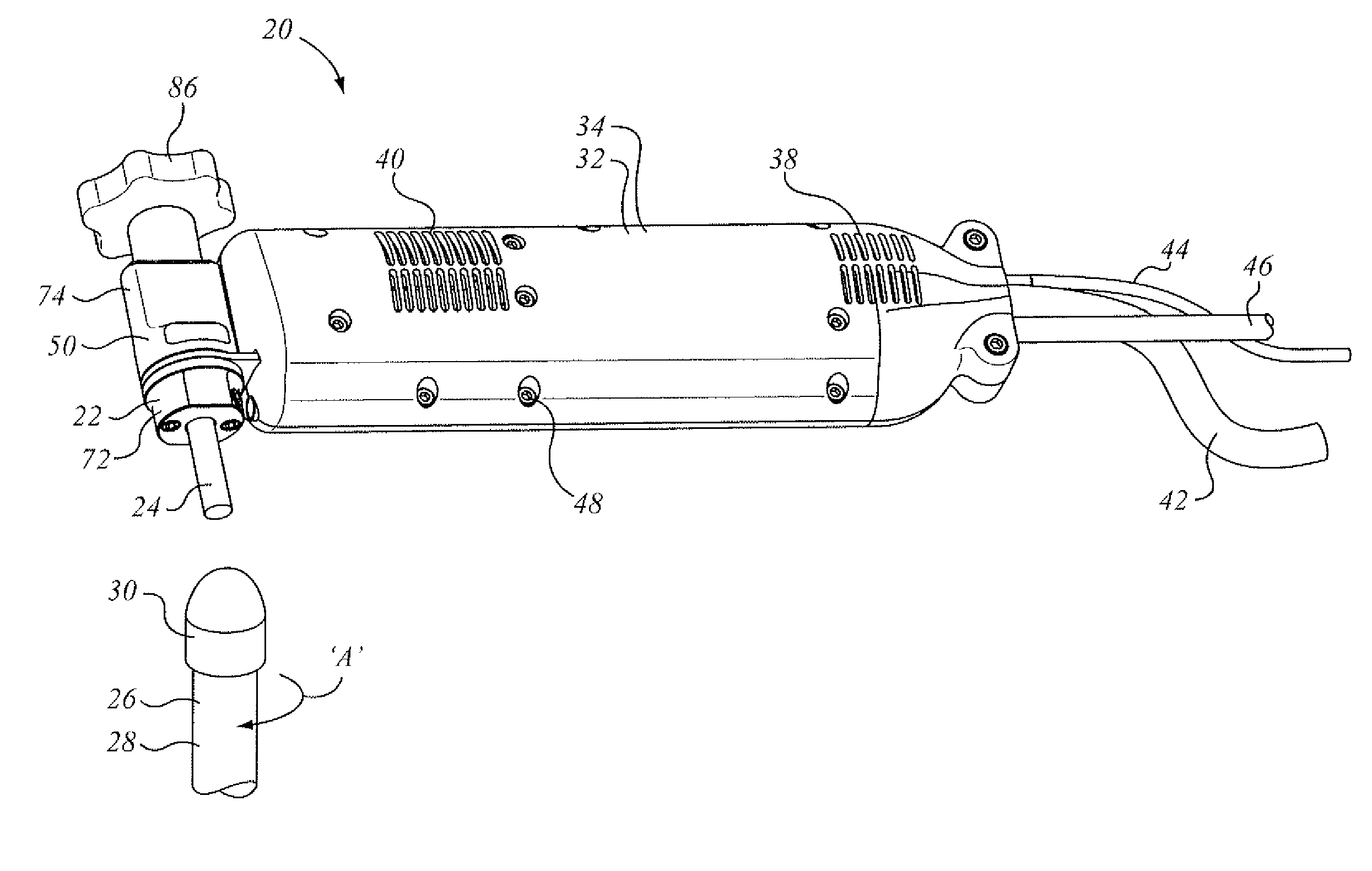
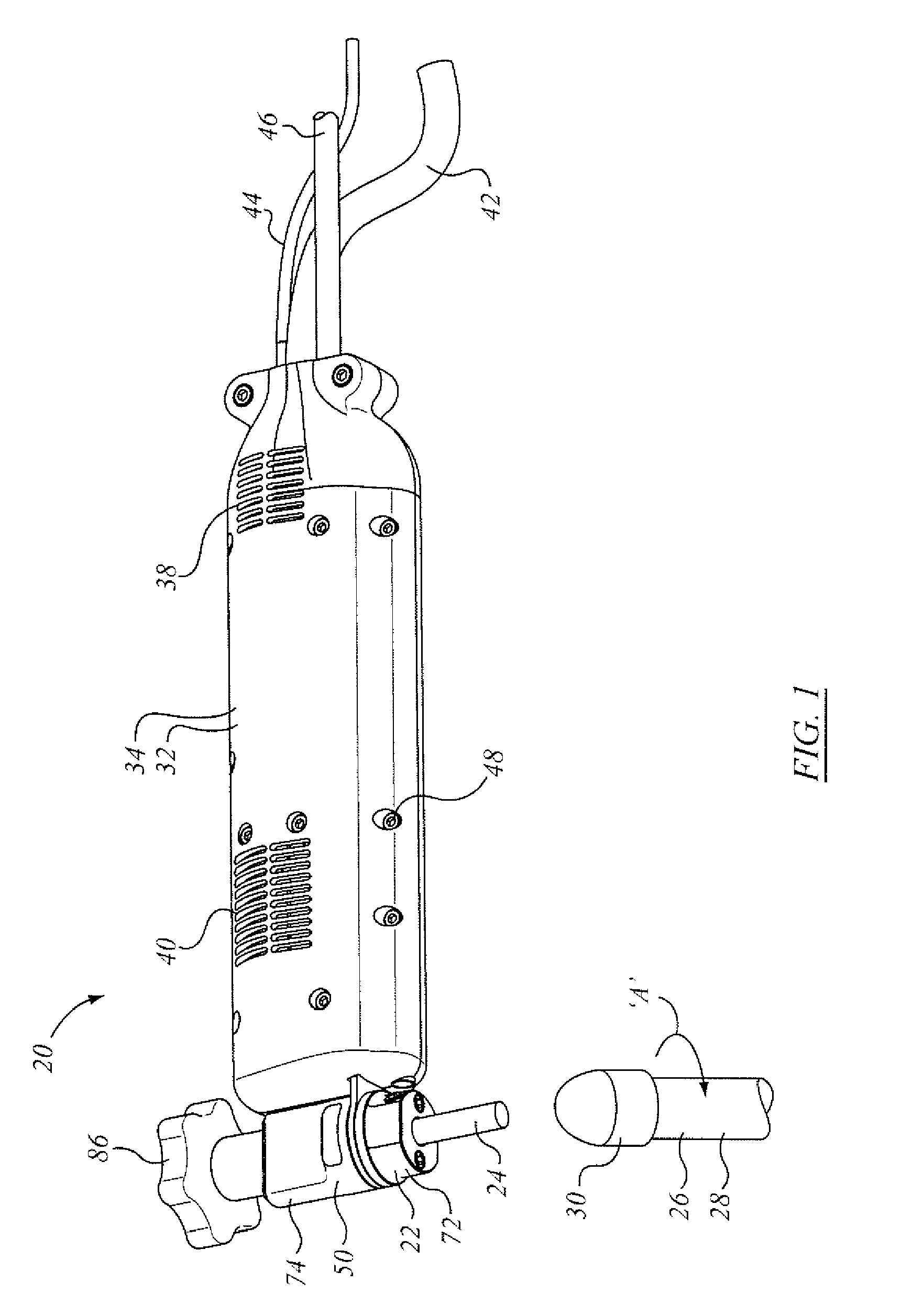
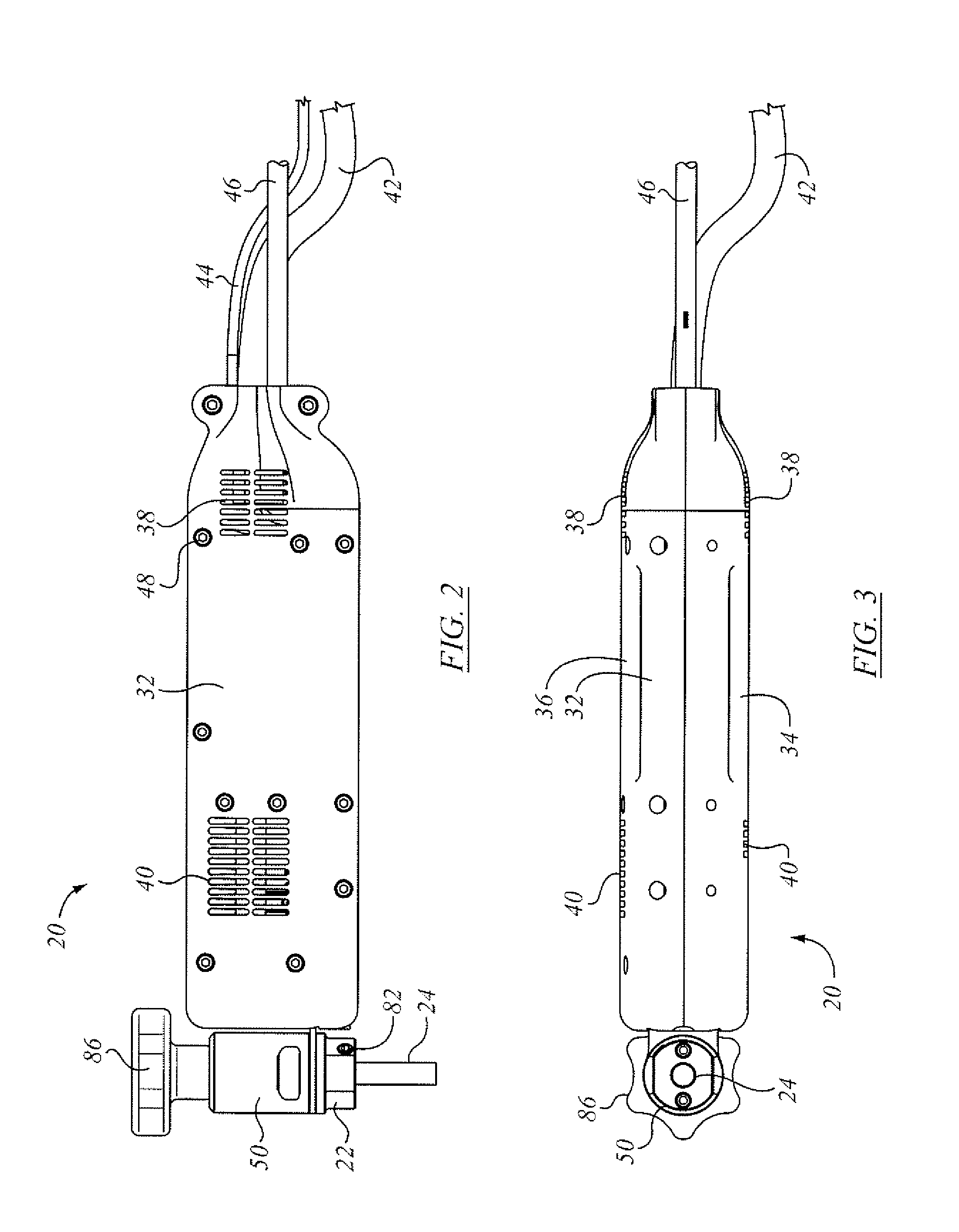
[0096]The description that follows, and the embodiments described therein, are provided by way of illustration of an example, or examples, of particular embodiments of the principles of aspects and features of the invention. These examples are provided for the purposes of explanation, and not of limitation, of those principles and of the invention. In the description, like parts are marked throughout the specification and the drawings with the same respective reference numerals. The drawings may be taken as being to scale, or generally proportionate, unless indicated otherwise. The photographic views may be taken as being to scale, or generally proportionate, unless indicated otherwise.

[0097]The scope of the invention herein is defined by the claims. Though the claims are supported by the description, they are not limited to any particular example or embodiment, and any claim may encompass processes or apparatus other than the specific examples described below. Other than as indicat...


PUM

PropertyMeasurementUnit
output frequencyaaaaaaaaaa
frequencyaaaaaaaaaa
frequencyaaaaaaaaaa

Abstract

A welding process involves a fixture for holding a workpiece and a welder, or welding electrode. The fixture imposes ultrasonic vibration on the workpiece. The welder vibrates during vibration, and is operable at a first voltage for welding and a second voltage for peening. The peening may occur while the weld metal is crystallizing. The welding process may be a process of welding two parts together, or of filling a groove or other feature, or of applying or restoring a surface, or of applying a hard facing or ceramic to a parent metal or object. The weld metal may be the same, or substantially the same, as the parent metal, or it may be different. The different material may be a ceramic material.

Description

[0001]This application claims the benefit of the priority of U.S. Provisional Patent Application Ser. No. 62 / 010,334, filed Jun. 10, 2014, the specification and drawings thereof being incorporated by reference in their entirety herein.[0002]This application claims the benefit under the Paris Convention of the priority of Chinese Patent Application 2013 1068 1469.1 filed Dec. 13, 2013, the specification and drawings thereof being incorporated herein by reference.[0003]This application claims the benefit under the Paris Convention of the priority of Chinese Patent Application 2013 1068 1599.1 filed Dec. 17, 2013, the specification and drawings thereof being incorporated herein by reference.FIELD OF THE INVENTION[0004]This application relates to methods and associated tools for welding.BACKGROUND OF THE INVENTION[0005]In a number of industries it may be helpful to be able to coat a metal substrate, or to join together by welding, or to make repairs by welding processes of existing obje...

Claims


Application Information

Patent Timeline
Patent Type & Authority Applications(United States)
IPC IPC(8): B23K9/04C23C4/18C23C4/10B23K9/30C23C4/12
CPCB23K9/04B23K9/30C23C4/18C23C4/10C23C4/125B23K37/00C23C4/131B23K37/0426
Inventor SCOTCHMER, NIGELLEUNG, DOMINIC CHEUK HUNGSHIJIE, DONGPING, LUOYING, CHANGHUIHU, WANGZHIXIONG, XIEZHONG, ZHENGWEI, YANGLIANZHUO, YANGQI, LIUYANQING, WANG
Owner HUYS IND
Why Eureka
Try Eureka