Methods and systems for continuous flow cell lysis in a microfluidic device

Active Publication Date: 2015-07-02
UNIV OF MARYLAND
View PDF8 Cites 20 Cited by
  • Summary
  • Abstract
  • Description
  • Claims
  • Application Information

AI Technical Summary

Benefits of technology

[0022]In some embodiments, the microfluidic channels are configured to support a flow rate sufficient to cause increased (mechanical) shear stress on the cells passing through the constructed regions as described herein. In some embodiments, the flow rate may be from about 20 to about 2000 μL/min. In other embodiments, the flow rate may be from about 20 to about 1000 μL/min. In still other embodiments, the flow rate may be from about 50 to about 500 μL/min. In further embodiments, the flow rate may be from about 50 to about 200 μL/min. In additional embodiments, the microfluidic device is configured to support a cell-lysis rate of 85-100%.
[0023]In some embodiments, the microfluidic device is made of a thermoplastic polymer. In additional embodiments, the mic

Problems solved by technology

This can be challenging when a large number of cells need to be processed in a short amount of time (such as when lysing the neutrophils recovered from patients with bloodstream infections) in a microfluidic channel.
For this case, the lysis must be “continuous-flow,” which implies that traditional chemical lysis techniques cannot be used.
While healthcare providers wait on current methods to process whole blood, it is necessary to use broad-range therapies to treat the infected patient, resulting in higher healthcare costs and increasing antibiotic resistance of pathogenic bacteria.
However, as the devices are silicon-based, they are not replica molded and thus are quite expensive and time-consuming to produce.
Fabricating the devices with soft-lithography would dramatically improve the cost, but unfortunately soft materials are not compatible with the mechanical lysis concept due to significant channel expansion that such materials experience under the high fluid pressure required for continuous flow cell lysis.
While it is clear

Method used


Image

  • Methods and systems for continuous flow cell lysis in a microfluidic device
  • Methods and systems for continuous flow cell lysis in a microfluidic device
  • Methods and systems for continuous flow cell lysis in a microfluidic device

Examples


Example

Example 1

[0079]The method for continuous flow cell lysis in a microfluidic device 800, according to some embodiments of the invention, was tested under four scenarios.

[0080]According to a first embodiment, the method was performed using a microfluidic device 800 comprising 18 microfluidic channels 502 each having 1 constricted region with a 3 μm constricted width (“single nozzle”).

[0081]According to a second embodiment, the method was performed by adding a detergent to the single-nozzle configuration above (“single nozzle+detergent”). The detergent comprised the addition of 0.1% Triton X-100 to the fluid flowing through the microfluidic device 800.

[0082]According to a third embodiment, the method was performed using a microfluidic device 800 comprising 20 microfluidic channels 502 each having 4 constricted regions with a 3 μm constricted width (“multi-nozzle (3 μm)”).

[0083]According to a fourth embodiment, the method was performed using a microfluidic device 800 comprising 20 microf...

Example

Example 2

[0087]The method for continuous flow cell lysis in a microfluidic device 800, according to some embodiments of the invention, was tested under two scenarios.

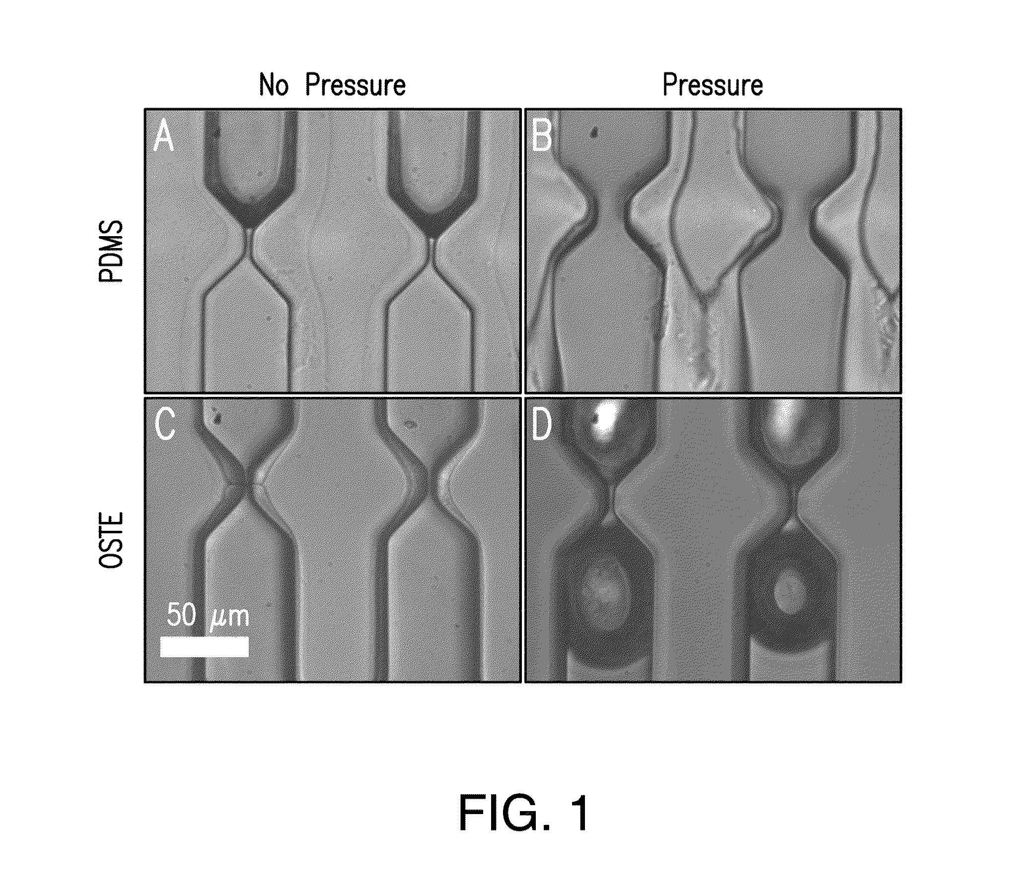
[0088]According to a first embodiment, the method was performed using a microfluidic device 800 comprising 40 microfluidic channels 502 each having 10 constricted regions 608, where the constricted width of the first five constricted regions 608 along the fluid flow path 510 was 6.5 μm and the constricted width of the last five constricted regions 608 along the fluid flow path 510 was 5 μm; the constricted length was 15 μm; the non-constricted width was 52 μm and the non-constricted length was 80 μm. The thermoplastic polymer was an OSTE polymer made from an OSTEmer Allyl 30 prepolymer (“OSTE”).

[0089]According to a second embodiment, the first embodiment was modified in that the thermoplastic polymer was PDMS (“PDMS”).

[0090]The fluid caused to be flowed through the microfluidic devices 800 comprised MDA-MB-231 human bre...


PUM

PropertyMeasurementUnit
Lengthaaaaaaaaaa
Lengthaaaaaaaaaa
Fractionaaaaaaaaaa

Abstract

The present invention relates to methods and systems for cell lysis in a microfluidic device. More specifically, embodiments of the present invention relate to methods and systems for rapid continuous flow mechanical cell lysis. In one embodiment, a microfluidic device includes one or more microfluidic channels, each channel comprising constricted regions and non-constricted regions separating the constricted regions, wherein the constricted regions are configured to disrupt the cellular membranes of cells in fluid flowing through the one or more microfluidic channels.

Description

CROSS-REFERENCE TO RELATED APPLICATIONS[0001]This application claims the benefit of U.S. Provisional Patent Application Ser. No. 61 / 922,447, filed on Dec. 31, 2013, and U.S. Provisional Patent Application Ser. No. 61 / 971,084, filed on Mar. 27, 2014, which are incorporated herein by reference in their entirety.BACKGROUND[0002]1. Field of the Invention[0003]The present invention relates to methods and systems for cell lysis. More specifically, embodiments of the present invention relate to methods and systems for rapid continuous flow cell lysis in a microfluidic device.[0004]2. Discussion of the Background[0005]Cell lysis has many different applications. To access the DNA from cells (including the enriched bacterial DNA in the circulating neutrophils of patients with bloodstream infections), it is necessary to lyse the cells. This can be challenging when a large number of cells need to be processed in a short amount of time (such as when lysing the neutrophils recovered from patients...

Claims


Application Information

Patent Timeline
IPC IPC(8): C12N5/078B32B37/00C12M1/00C12N1/20C12N1/06
CPCC12N5/0634C12N1/20C12N1/066B32B2305/72C12M99/00B32B37/0076C12N2509/10C12M47/06B01L3/502707B01L3/502761B01L2200/0647B01L2300/0816B01L2400/086
Inventor WHITE, IAN M.BURKE, JEFFREYPANDIT, KUNAL
Owner UNIV OF MARYLAND
Why Eureka
Try Eureka