

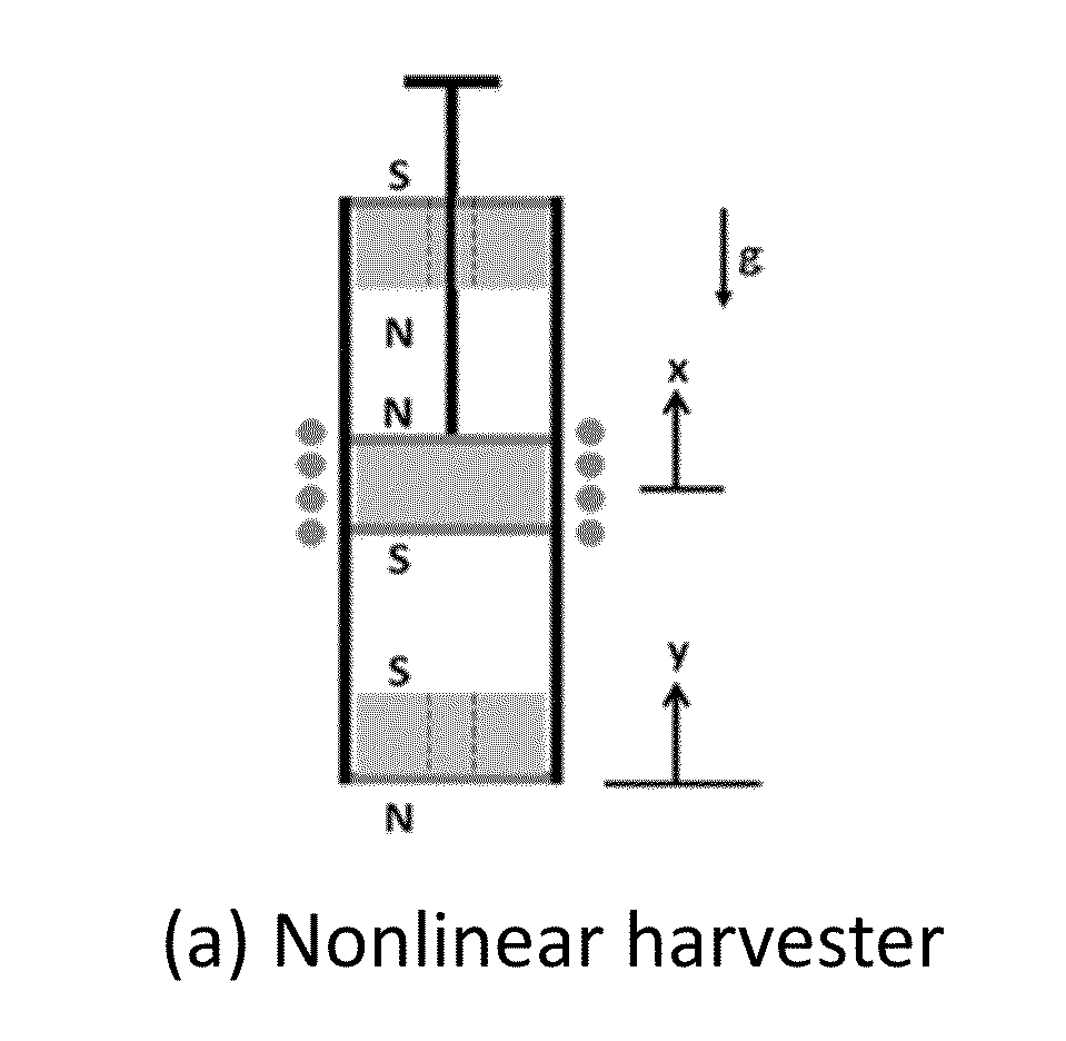
Energy Harvesting System with Multiple Cells
a technology of energy harvesting system and energy harvesting cell, which is applied in the direction of mechanical energy handling, mechanical equipment, machines/engines, etc., can solve the problems of limited application of wireless sensors, limited environmental protection of conventional batteries, and limitations of conventional batteries, so as to reduce surface contact area and reduce friction induced energy loss
- Summary
- Abstract
- Description
- Claims
- Application Information
AI Technical Summary
Benefits of technology
Problems solved by technology
Method used
Image

Examples
Embodiment Construction
[0019]The following description is provided in the context of particular designs, applications and the details, to enable any person skilled in the art to make and use the invention. However, for those skilled in the art, it is apparent that various modifications to the embodiments shown can be practiced with the generic principles defined here, and without departing the spirit and scope of this invention. Thus, the present invention is not intended to be limited to the embodiments shown, but is to be accorded the widest scope consistent with the principles, features and teachings disclosed here.
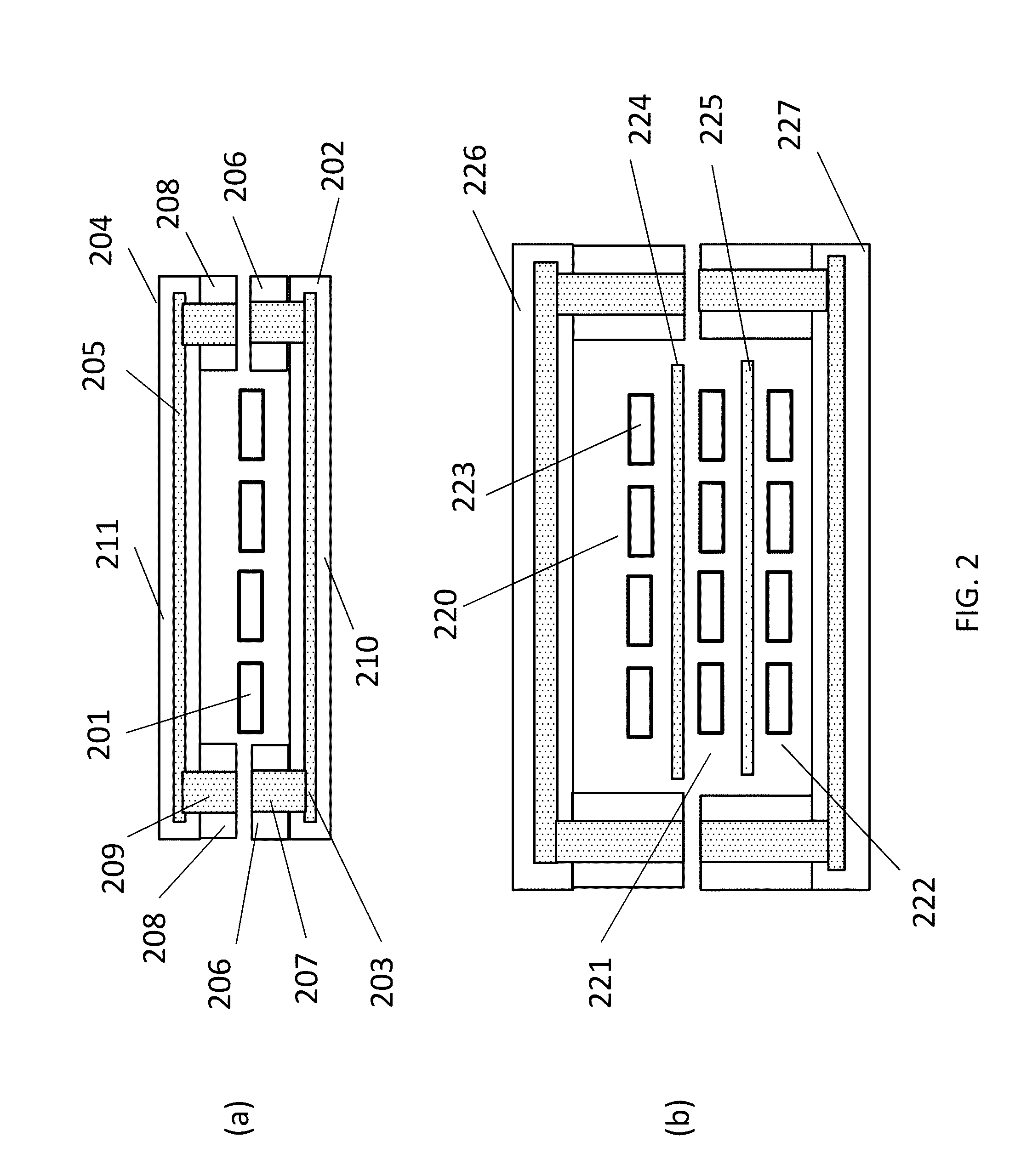
[0020]FIG. 2(a) shows one of the embodiments of the proposed energy harvesting system with array of energy harvesting cell 201 arranged as one single row of cells, while FIG. 2(b) shows another embodiments, whose energy harvesting cells are arranged in multiple rows. For simplicity, no solder pads for the assembly are shown in FIG. 2.
[0021]In FIG. 2(a) of the proposed energy harvesting syste...
PUM
 Abstract
Description
Claims
Application Information