Acoustic radiation force magnetic resonance imaging

a magnetic resonance imaging and magnetic resonance technology, applied in the field of magnetic resonance guided high intensity focused ultrasound, can solve the problems of reducing treatment efficiency, affecting the clinical performance of the system, and affecting the accuracy of tissue displacement, so as to speed up the acquisition of data, shorten the duration, and accurate tissue displacement value

a magnetic resonance imaging and magnetic resonance technology, applied in the field of magnetic resonance guided high intensity focused ultrasound, can solve the problems of reducing treatment efficiency, affecting the clinical performance of the system, and affecting the accuracy of tissue displacement, so as to speed up the acquisition of data, shorten the duration, and accurate tissue displacement value

US20150190659A1Active Publication Date: 2015-07-09PROFOUND MEDICAL

Image

  • Acoustic radiation force magnetic resonance imaging
  • Acoustic radiation force magnetic resonance imaging
  • Acoustic radiation force magnetic resonance imaging

Examples


Embodiment Construction

[0061]Like numbered elements in these figures are either equivalent elements or perform the same function. Elements which have been discussed previously will not necessarily be discussed in later figures if the function is equivalent.

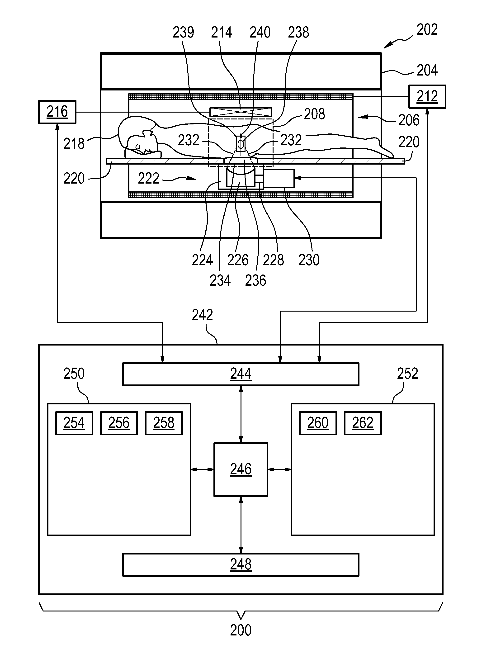
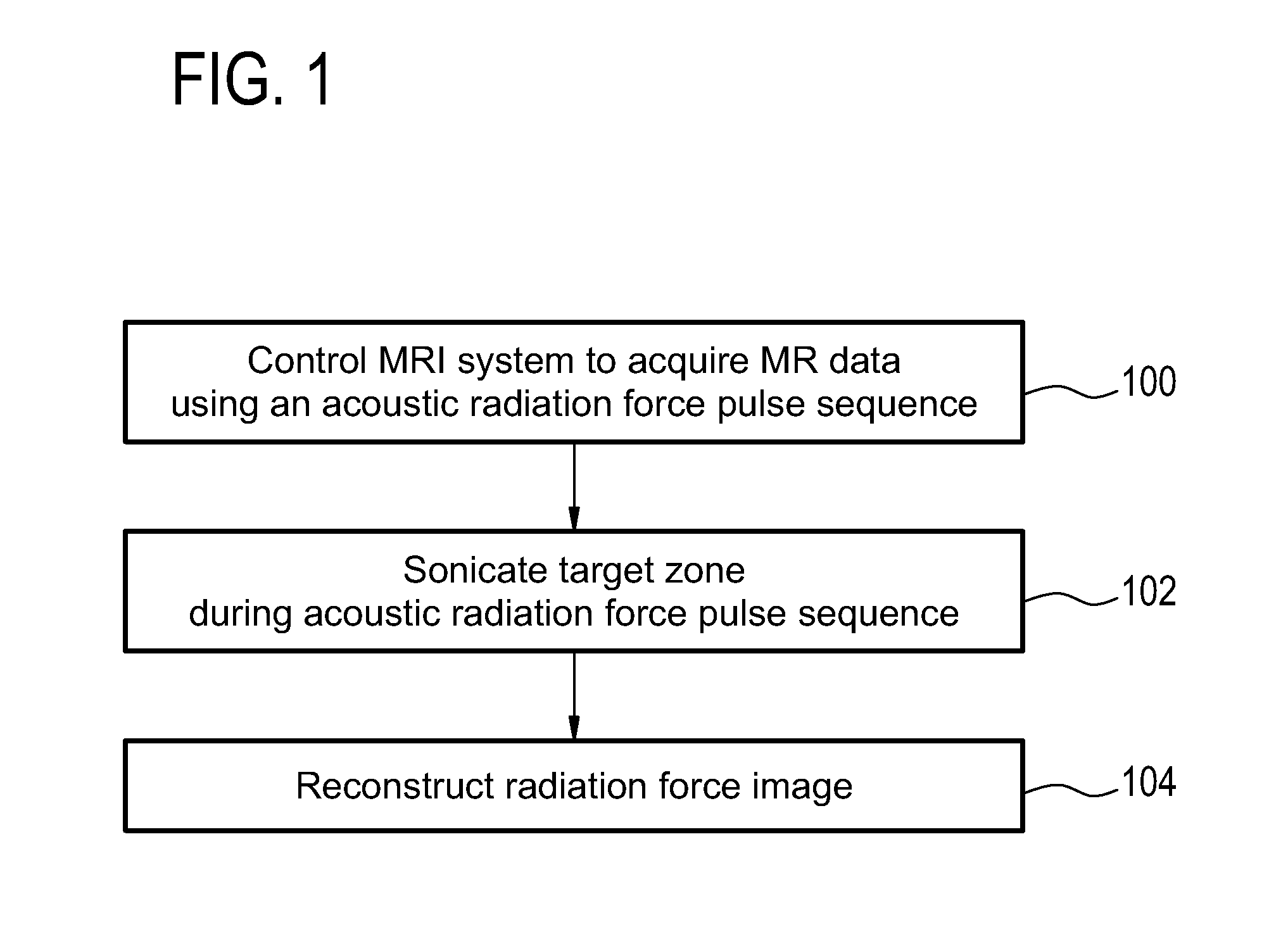
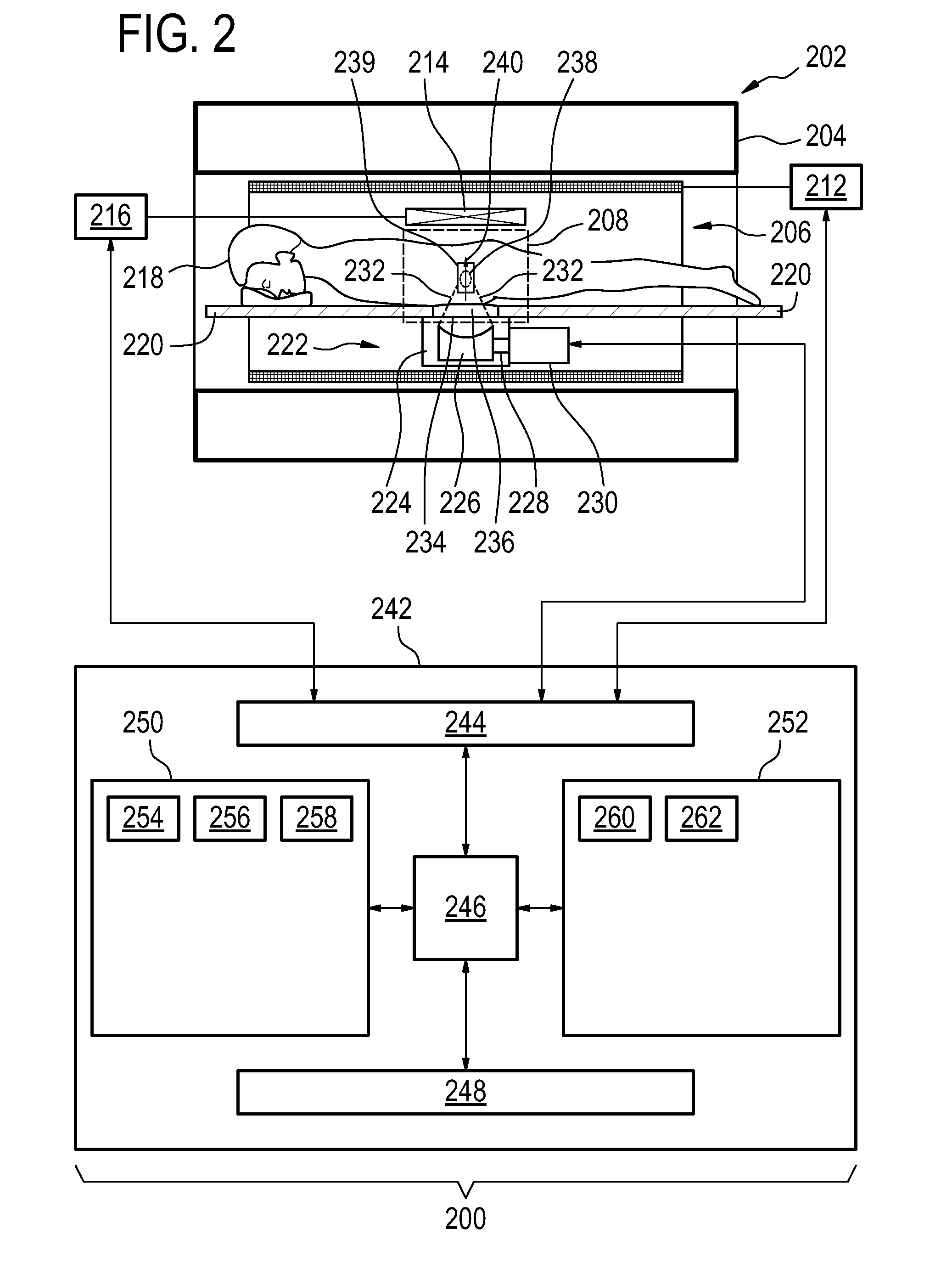
[0062]FIG. 1 shows a flowchart which illustrates a method according to an embodiment of the invention. First in step 100 a magnetic resonance imaging system is controlled to acquire magnetic resonance data using a pulse sequence. The pulse sequence comprises an acoustic radiation force imaging pulse sequence. The acoustic radiation force imaging pulse sequence comprises an excitation pulse. The acoustic radiation force imaging pulse sequence comprises a multi-dimensional gradient pulse applied during the radio-frequency excitation pulse for selectively exciting the region of interest. The region of interest comprises a predetermined volume that encompasses the target zone and at least a portion of the beam axis. Next in step 102 a high-intensity focused...


PUM


Abstract

The invention provides for medical instrument (200, 400) comprising a magnetic resonance imaging system (202) and a high intensity focused ultrasound system (222). A processor (246) controls the medical instrument. Instructions cause the processor to control (100) the magnetic resonance imaging system to acquire the magnetic resonance data using a pulse sequence (254). The pulse sequence comprises an acoustic radiation force imaging pulse sequence (500, 600). The acoustic radiation force imaging pulse sequence comprises an excitation pulse (512) and a multi-dimensional gradient pulse (514) applied during the radio frequency excitation pulse for selectively exciting a region of interest (239) encompassing a target zone and at least a portion of the beam axis. The instructions cause the processor to control (102) the high intensity focused ultrasound system to sonicate the target zone during the acoustic radiation force imaging pulse sequence and reconstruct (104) a radiation force image (258) using the magnetic resonance data.

Description

TECHNICAL FIELD[0001]The invention relates to magnetic resonance guided high intensity focused ultrasound, in particular it relates to the determination of tissue displacement by high intensity focused ultrasound using magnetic resonance imaging.BACKGROUND OF THE INVENTION[0002]In high intensity focused ultrasound (HIFU) an array of ultrasonic transducer elements are used to form an ultrasonic transducer. Supplying alternating current electrical power to the transducer elements causes them to generate ultrasonic waves. The ultrasonic waves from each of the transducer elements either add constructively or destructively at different locations in the beam path. By controlling the phase of alternating current electrical power supplied to each of the transducer elements the focal point or volume into which the ultrasound power is focused may be controlled.[0003]High-intensity focused ultrasound (HIFU) therapy of tumors requires a high degree of spatial accuracy in order to avoid damaging...

Claims


Application Information

Patent Timeline
09 Jul 2015
Publication
US20150190659A1
IPC
A61N7/02; A61B5/00; A61B5/01; G01R33/54; G01R33/561
CPC
A61B2505/05; A61N7/02; G01R33/543; A61N2007/0039; A61B5/015; A61B5/7278; A61B5/748; G01R33/5611
Inventors
KOHLER, MAX OSKAR