One difficulty of using LEDs stems from the large mismatch between the
alternating current (AC) mains voltage, typically in the range of 100 VAC-277 VAC and the voltage of a single LED which is typically on the order of 1-2V.
Another difficulty stems from the range of LED voltages as a function of temperature, manufacturer tolerances, and different manufacturer specifications.
However, this only alleviates part of the issue since it is typically not feasible to place so many LEDs in series to match the AC mains voltage.
Furthermore, placing devices in series only partly addresses the issue of voltage matching and does not address the issue of AC-to-DC mismatch or LED
voltage variation.
However, this solution is very inefficient, has lifetime issues due to the heating of the
resistor, and also leads to a very poor utilization of the available LED power due to the extremely high
ripple current produced by the LED.
While this typical type of driver provides a
DC voltage to the LED, these driver types suffer from several drawbacks.
One drawback of these drivers is the use of limited-lifetime components which gives the driver a much lower effective lifetime than the LED itself.
These low-lifetime components not only reduce the cost-effectiveness of the overall LED solution, but they also limit the applications to use over relatively small temperature variations.
A further drawback of these LED drivers is their inability to provide a lighting solution which provides a specific
light level across temperature and manufacturing tolerance variations.
Small changes in LED voltage can lead to a large change in LED current and consequently to a large change in light output.
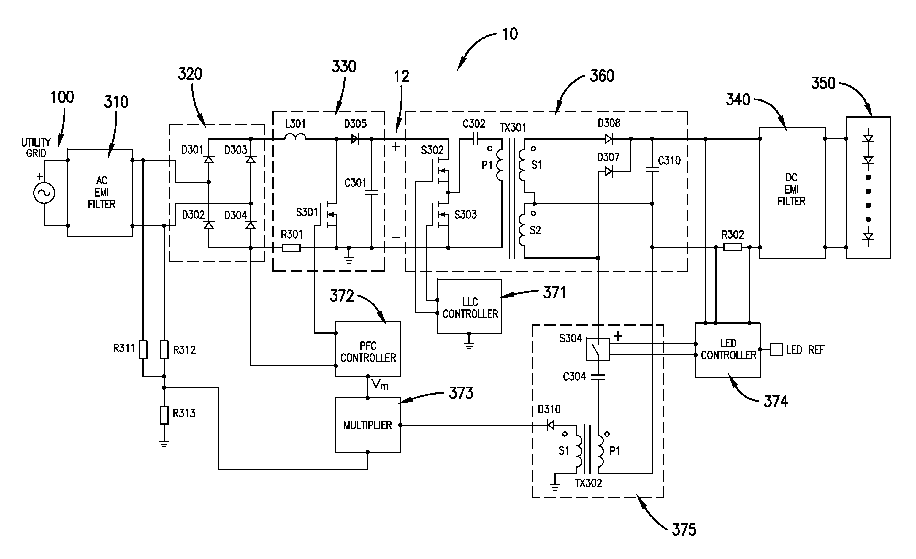
Fixed-frequency continuous-conduction-mode pulse-width-modulation typically requires expensive controllers, very large inductors, and large EMI filtering components to reduce the
noise created at the
single pulse-width-modulation frequency.
Furthermore, fixed-frequency controllers can have high switching losses since the frequency is held constant regardless of the waveform amplitude.
On the other hand, variable-frequency critical-conduction-mode pulse-width-modulation is inefficient due to the very high
ripple current produced in the inductor, and therefore also requires large filters to reduce electro-magnetic-interference (EMI).
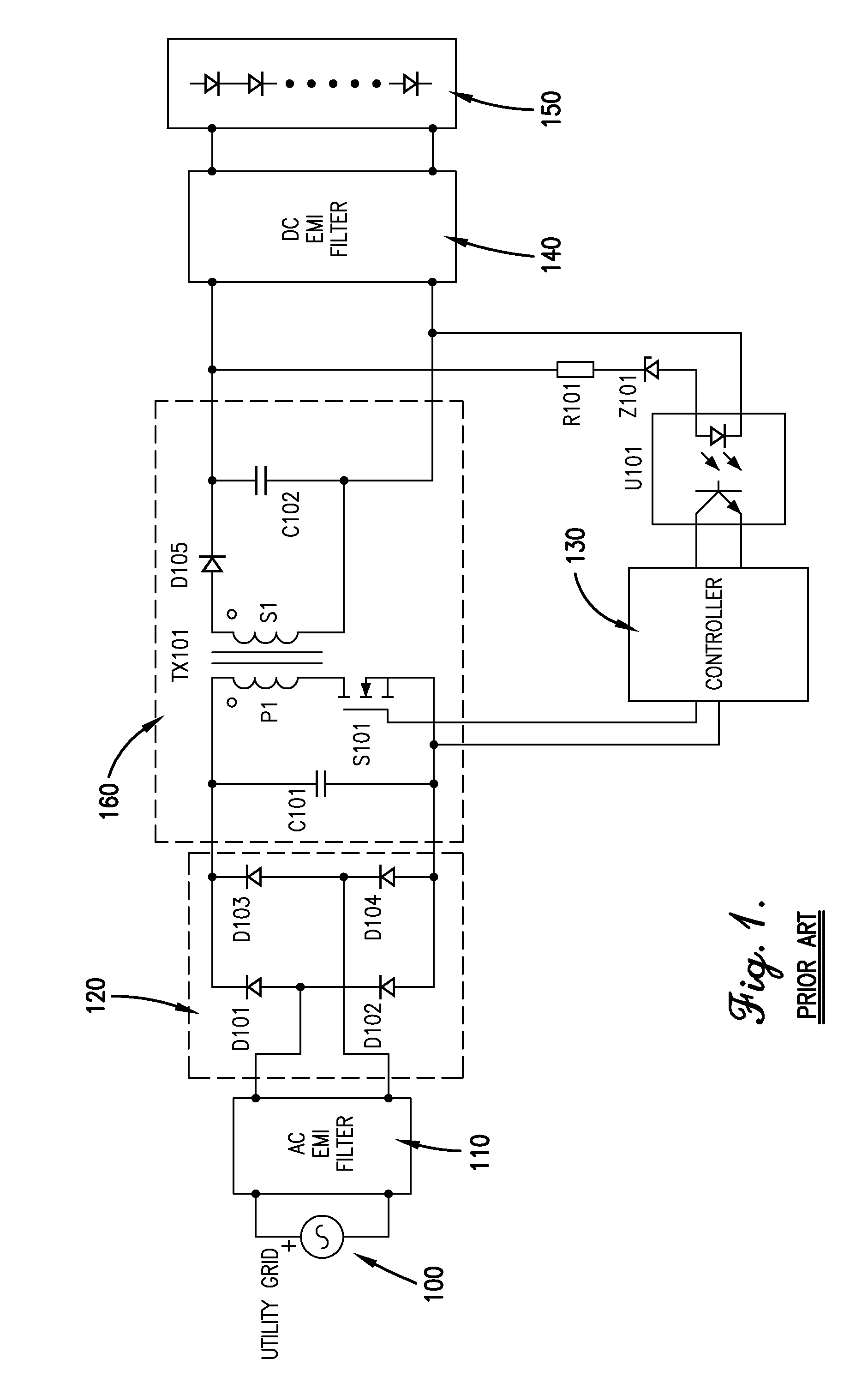
While this prior art converter in FIG. 1 offers a very inexpensive alternative to drive LED strings, it also has many limitations and drawbacks.
This lifetime issue can significantly
impact the cost-effectiveness of the LED solution to replace other type of lighting, particularly in higher temperature applications where the
electrolytic capacitor lifetime will be even lower.
3) Optocoupler U101 also has a limited lifetime causing the same issues as the limited lifetime of the
electrolytic capacitor.
4) The electrolytic
capacitor and optocoupler will limit operation of the
LED driver to indoor applications due to temperature limitations of both parts.
5) The high pulse currents drawn by the input charging circuit cause significant
distortion of the input current and are only allowed for small
converters (e.g. below 75 W).
6) Isolated
converters such as flyback converters tend to have a relatively low efficiency.
Most pulse-width-modulation converters that must adjust the output voltage for changes in the input voltage suffer from higher losses compared with converters that do not regulate output voltage versus input voltage.
Addition of the power-factor-correction converter solves only the issue of high pulse currents and
distortion in the grid current, without addressing the other issues.
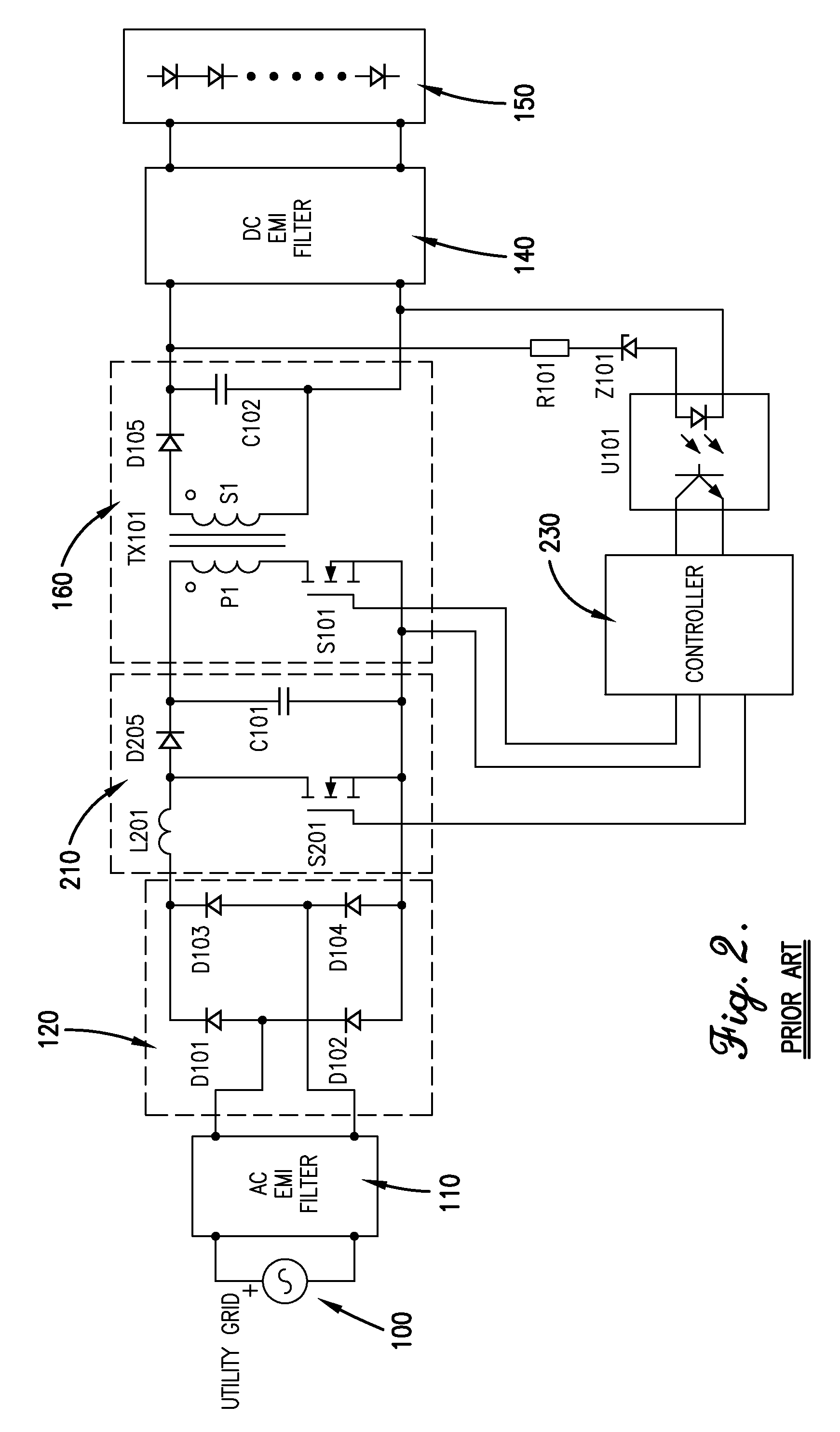
Furthermore, typical methods of operating power-factor-correction converters create additional issues.
A great drawback to this control method is that the peak-to-peak ripple current through L201 is always twice as large as the instantaneous current that is drawn from the ac grid.
This method is typically used for relatively low power power-factor-correction converters less than approximately 120 W due to the
cost savings that occur from using a
diode D205 which may have some
recovery losses.
Some drawbacks to this method of control include the following: relative complexity of the control compared with the critical
conduction mode method, similar ripple amplitude near the zero-crossings of the AC grid current compared with the peak of the grid current, thus causing increased
harmonic distortion, and substantial EMI
noise concentrated at multiples of the pulse-width-modulation frequency.

