Hollow fiber membrane module and filtering method

a technology of hollow fiber membrane and filtering method, which is applied in the direction of membranes, filtration separation, separation processes, etc., can solve the problems of hollow fiber membrane breaking, particulates leakage into the filtrate, and the water flow may not be eliminated sufficiently, so as to achieve the effect of reliable adjustment, low speed, and suppression of hollow fiber membrane breakag

Active Publication Date: 2015-07-16
ASAHI KASEI CHEM CORP
View PDF1 Cites 31 Cited by
  • Summary
  • Abstract
  • Description
  • Claims
  • Application Information

AI Technical Summary

Benefits of technology

[0018]In addition, in the above-described embodiment, the hollow fiber membrane module may be configured such that the value resulting from the division of the height of the plate-like bias regulating members by the thickness of the adhesive fixation layer may be at least 0.5 and less than 0.7 and that the value resulting from the division of the height of the rod-like bias regulating members by the thickness of the adhesive fixation layer may be at least 0.6 and less than 0.8. The use of the bias regulating members within such ranges allows more reliable adjustment of the distribution of the hollow fiber membranes in the outer end surface and in the inner end surface.
[0019]Furthermore, in the above-described embodiment, the hollow fiber membrane module may be configured such that a ratio between a height h of the straightening cylinder from the inner end surface of the adhesive fixation layer and an inner diameter d of the straightening cylinder is at least 0.7 and less than 1.1. With this range, water to be treated which has been introduced into the hollow fiber membrane module can be prevented from coming into direct contact with a hollow fiber bundle, and a velocity at which the water to be treated with a direction thereof changed by the straightening cylinder flows into the hollow fiber membranes can be kept at a low speed. Thus, breakage of the hollow fiber membranes can further be suppressed.
[0020]Additionally, in the above-described embodiment, the hollow fiber membrane module may be configured such that the inner end surface side of the bias regulating member is tapered. The use of such bias regulating member allows the bias regulating member to be installed without damaging the hollow fiber membranes when the bias regulating member is inserted into the bundle of hollow fiber membranes.
[0021]Furthermore, a filtration method using the hollow fiber membrane module according to the above-described embodiment may comprise supplying water to be treated to an area outside the hollow fiber membranes in the housing and retrieving treated water having permeated the hollow fiber membranes through openings of the hollow fiber membranes. Thus, the filtration method using each of the above-described hollow fiber membrane modules enables efficient filtration of a large amount of water to be treated.
[0022]Additionally, in the above-described filtration method, the treated water may be ultrapure water. Even in an application such as an ultrapure water application which demands water with stably high quality, each of the above-described hollow fiber membrane modules are unlikely to cause the hollow fiber membranes to be broken and suffers only a low pressure loss resulting from filtration. This allows preferable filtrate to be continuously generated.
[0023]The above-described hollow fiber membrane module and filtration method according to the embodiment prevent the hollow fiber membranes from being broken to allow water with stably high quality to be generated over a long period of time.

Problems solved by technology

However, even with the insertion of the insertion object, the bias of the water flow may not sufficiently be eliminated when the amount of filtrate per module is increased.
This may cause the hollow fiber membranes to be broken, with the result that particulates leak out into the filtrate.

Method used


Image

  • Hollow fiber membrane module and filtering method
  • Hollow fiber membrane module and filtering method
  • Hollow fiber membrane module and filtering method

Examples


example 1

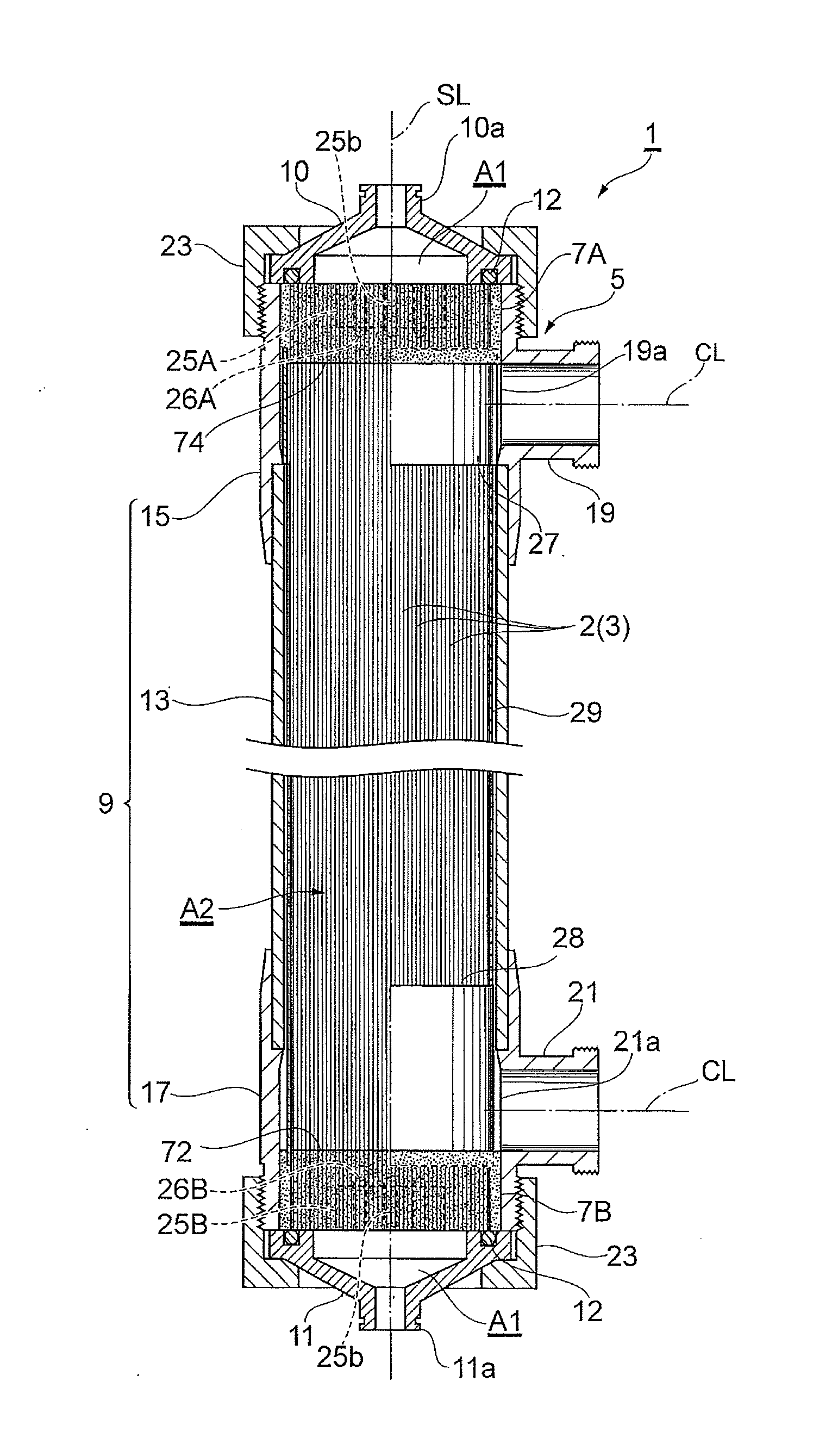
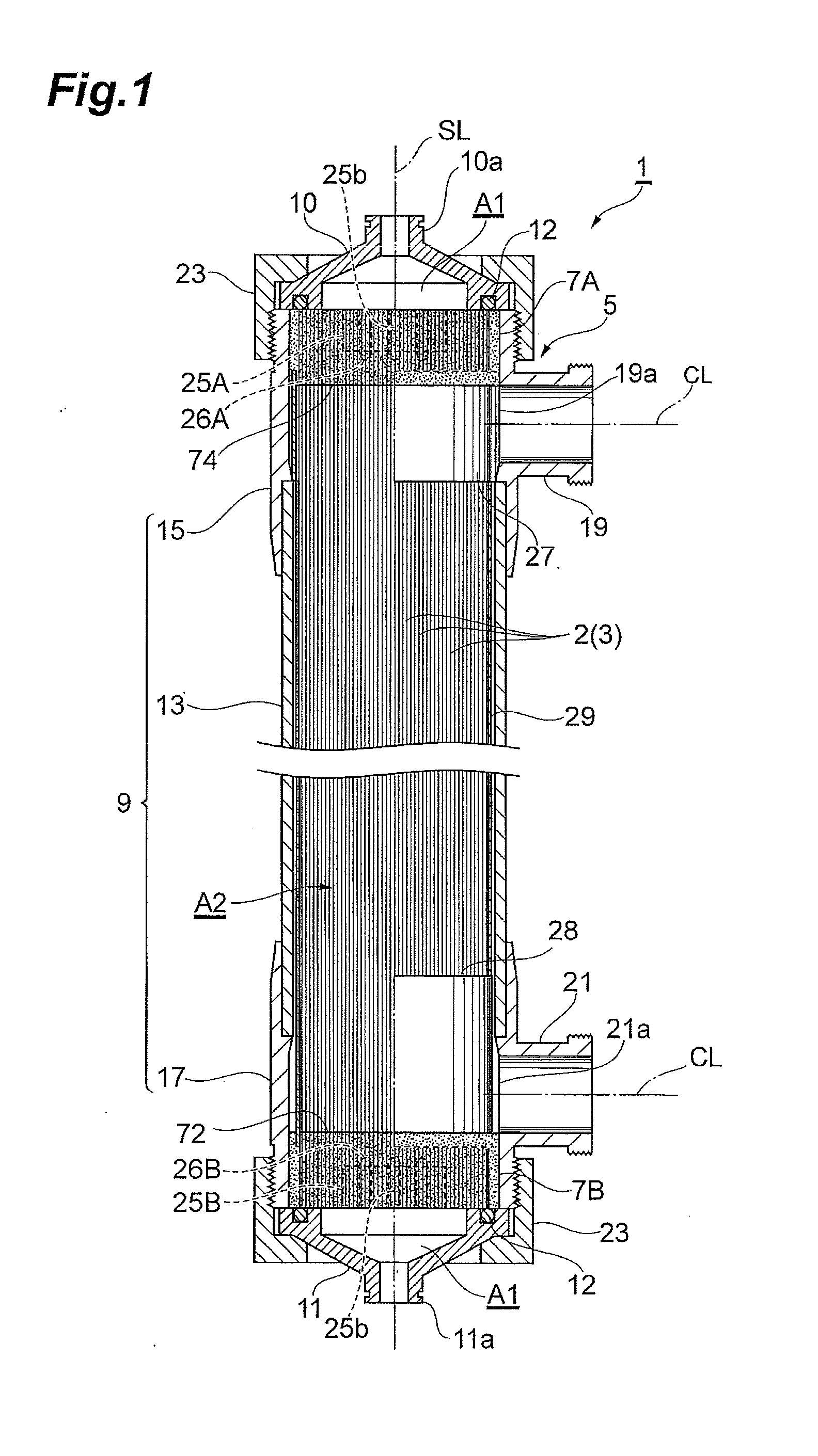
[0127]A filtration operation was performed using a hollow fiber membrane module constructed by covering 11600 hollow fiber membranes of polysulfone with a polyethylene net with a wire diameter of 0.5 mm as a contact prevention member, placing the hollow fiber membranes covered with the net in a polysulfone housing, and fixing the housing at the opposite ends thereof with an epoxy resin.

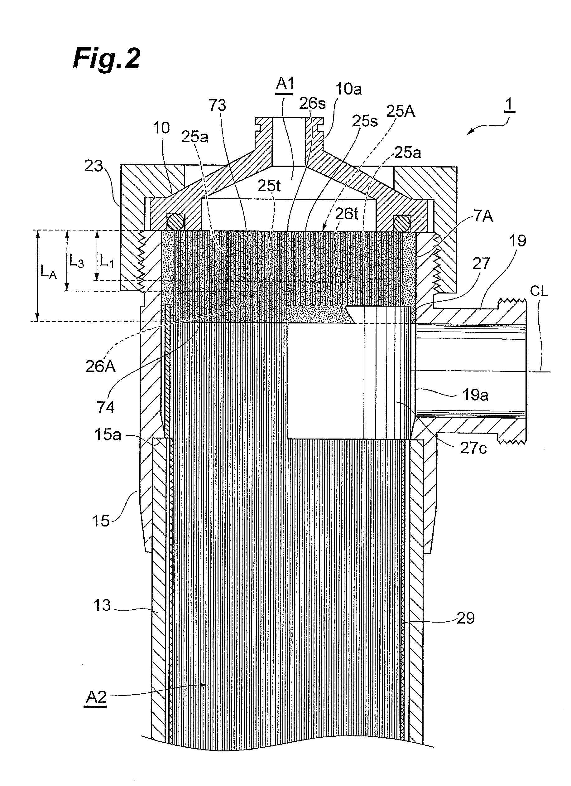
[0128]Cross shapes (cross plates) of height 70 mm, width 138 mm, and thickness 5 mm and cylindrical insertion rods of height 75 mm and diameter 10 mm were inserted into each of the ends of the bundle of hollow fiber membranes as bias regulating members using the same epoxy resin as that used to form the adhesive fixation layers. Furthermore, the cross plates were placed in each of the adhesive fixation layers so as to avoid facing the lower nozzle or the upper nozzle. The separation distance between the cross plates and the straightening cylinder was 22 mm. The height of the cross plates in the adhesi...

example 2

[0134]A hollow fiber membrane module was produced and a filtration operation was performed as is the case with the first example except that, as the straightening cylinder, a cylindrical component of inner diameter 140 mm and height 185 mm was used.

[0135]Two months after the start of operation, the number of particulates of at least 0.1 μm in the filtrate was measured. Then, the number was 70 pcs / L. At that point in time, operation was stopped, and a leak check was conducted under an external pressure using air (the pressure was maintained at 0.1 MPa for two minutes). As a result of the leak check, air leakage from the cut end surface of the module was observed but only at two points.

[0136]The module was disassembled, and the hollow fiber membranes were removed. For evaluation of the performance of the hollow fiber membranes, the outer surface-equivalent amount of transmitted water was measured. Then, the amount was 490 L / m2 / hr, indicating substantially no change. Furthermore, the b...

example 3

[0138]A hollow fiber membrane module was produced and a filtration operation was performed as is the case with the first example except that, as the bias regulating member, cross shapes (cross plates) of height 78 mm, width 138 mm, and thickness 5 mm and cylindrical insertion rods of height 83 mm and diameter 10 mm were used.

[0139]Two months after the start of operation, the number of particulates of at least 0.1 μm in the filtrate was measured. Then, the number was 100 pcs / L. At that point in time, operation was stopped, and a leak check was conducted under an external pressure using air (the pressure was maintained at 0.1 MPa for two minutes). As a result of the leak check, air leakage from the cut end surface of the module was observed but only at three points.

[0140]The module was disassembled, and the hollow fiber membranes were removed. For evaluation of the performance of the hollow fiber membranes, the outer surface-equivalent amount of transmitted water was measured. Then, t...


PUM

PropertyMeasurementUnit
inner diameter/outer diameteraaaaaaaaaa
outer diameteraaaaaaaaaa

Abstract

A hollow fiber membrane module comprising a bundle of hollow fiber membranes, a housing, an adhesive fixation layer, an inlet and outlet, at least one bias regulating member, and at least one straightening cylinder, in which the bias regulating member is contained in the adhesive fixation layer, the adhesive fixation layer comprises an outer end surface and an inner end surface inside the straightening cylinder, at least some of spaces between the hollow fiber membranes are at least three times as large as an outer diameter of the hollow fiber membrane on the outer end surface of the adhesive fixation layer, and the spaces between the hollow fiber membranes and a space from the hollow fiber membranes to the straightening cylinder are all less than three times as large as the outer diameter of the hollow fiber membrane on the inner end surface of the adhesive fixation layer.

Description

BACKGROUND OF THE INVENTION[0001]1. Field of the Invention[0002]The present invention relates to a hollow fiber membrane module suitable as a final filter that removes particulates in water to be treated in a ultrapure water manufacturing process.[0003]2. Related Background Art[0004]In a line where ultrapure water used to manufacture electronic and electric components such as semiconductors and display elements, a membrane filter module is used as a final filter that removes particulates from ultrapure water manufactured using microfiltration membranes and an ion exchange resin or reverse osmosis membranes immediately before the ultrapure water is supplied to a use point. As a membrane filter module for this application, an external-pressure hollow fiber membrane module that supplies raw water to the outside of a hollow fiber membrane to filter the water is used because the hollow fiber membrane module has the advantage of enabling an increase in filtration flow rate per module.[000...

Claims


Application Information

Patent Timeline
Patent Type & Authority Applications(United States)
IPC IPC(8): C02F1/44B01D63/04
CPCC02F1/444C02F2103/04B01D63/04B01D63/02B01D63/021B01D63/022B01D2313/23
Inventor SHIKI, SATOSHI
Owner ASAHI KASEI CHEM CORP
Why Eureka
Try Eureka