

Method and apparatus for multiplexed power and data supply via a two-wire data communication cable
a data communication cable and multiplexing technology, applied in data switching networks, instruments, data switching details, etc., can solve the problems of limiting the solution to star topologies in wiring, limiting the solution to twisted-pair wiring, and unable to achieve daisy-chaining. , to achieve the effect of efficient powering loads
- Summary
- Abstract
- Description
- Claims
- Application Information
AI Technical Summary
Benefits of technology
Problems solved by technology
Method used
Image

Examples
first embodiment
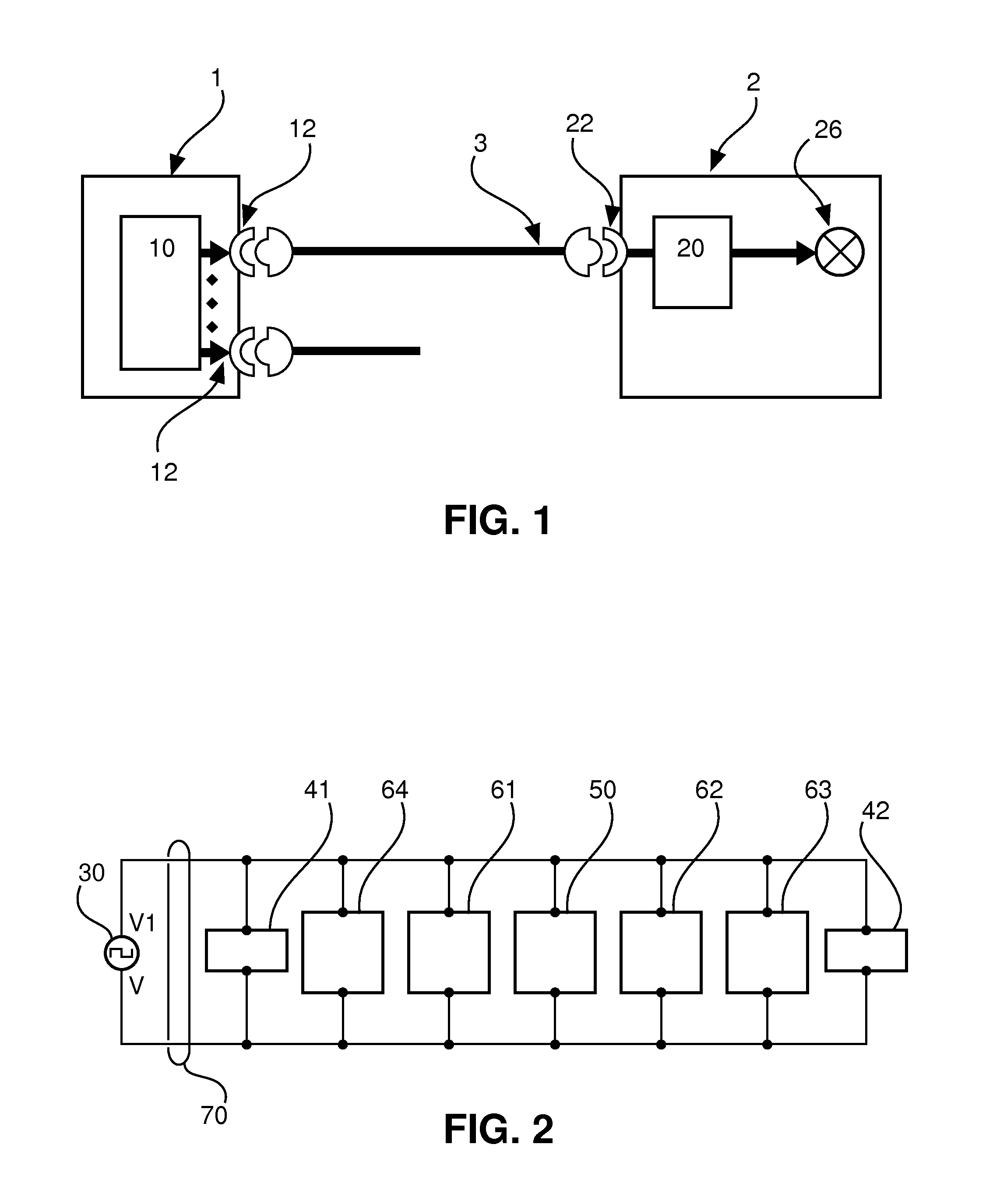
[0031]FIG. 2 shows a schematic block diagram of a network system according to A number of loads or load devices 61 to 64 (e.g., two lamps 61, 62, a sensor 63 and another load 64) and a controller 50 are connected to a coaxial cable 70, wired in a bus structure, where time division multiplexing is applied to share the medium for power and data transport and known data arbitration methods of Ethernet 10Base2 may be used to share the medium for multiple communication streams during the data transport phase. At least on one end, the system is powered by a supply device 30 which generates a potential V1 at the upper wire of FIG. 2 and a potential V at the lower wire. Both ends of the two-wire cable are terminated by respective termination units 41, 42, which may comprise at least one resistor or other impedances or which may even comprise circuits with semiconductor devices. Within the cable length between the terminations 41, 42, the multiple loads 61 to 64 are connected to the two sig...
second embodiment
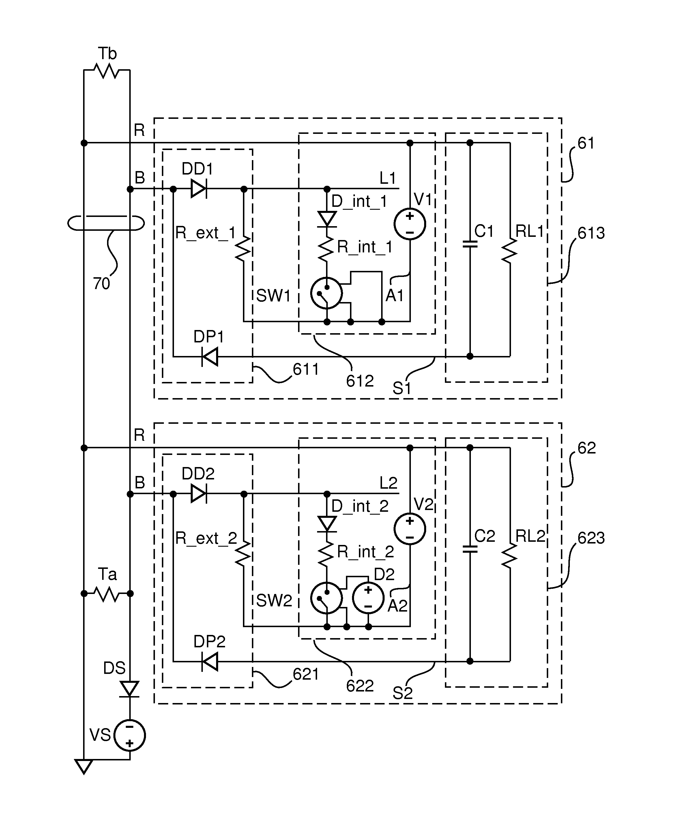
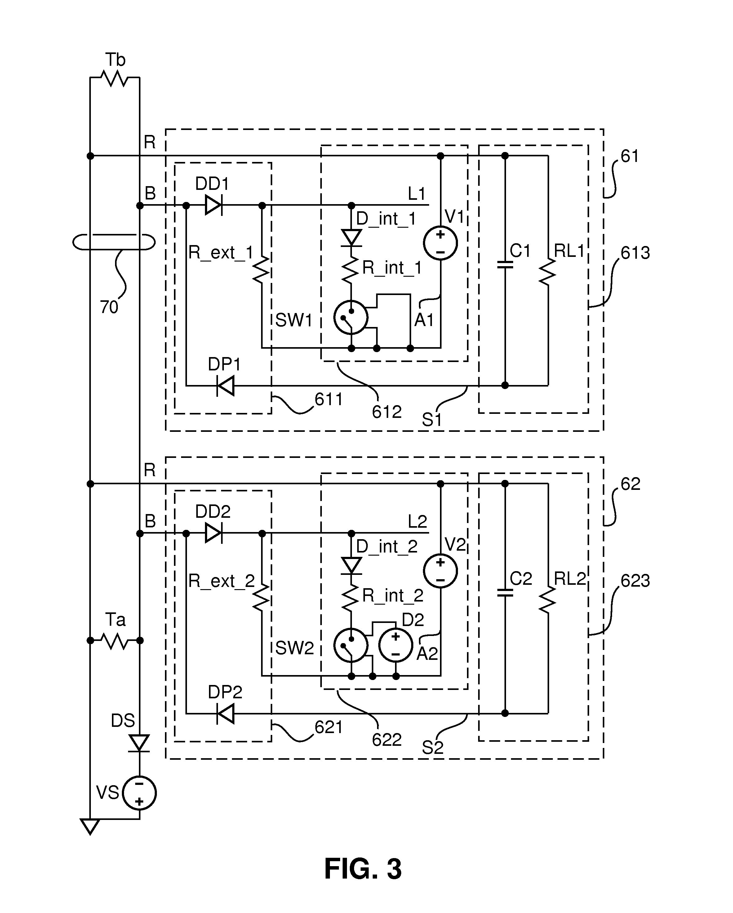
[0035]FIG. 2 shows an exemplary two-lamp system with more detailed circuit diagrams of lamp devices 61, 62 according to a A pulsed power source VS applies a negative powering voltage via coupling diode DS to the bus-type structure of the coaxial cable 70 for a fraction of the time. Two termination resistors Ta and Tb are connected between the wires of the coaxial cable. Furthermore, the two lamp devices 61, 62 are connected between the two wires.
[0036]Each lamp device 61, 62 has a power storing and consuming part 613, 623 each comprising a respective capacitor C1, C2 and a load resistor RL1, RL2. In a real lamp device, there might be a string of light emitting diodes (LEDs) or a LED driver present in the power storing and consuming part 613, 623. Basically, powering of the load may be one reason for using such a system.
[0037]Moreover, a simplified circuit of a data transfer or transmission part 612, 622 of a 10Base2 physical layer protocol interface is depicted for each of the lamp...
third embodiment
[0041]Termination of the bus structure of the coaxial cable 70 is important for proper data communication. However, the traditional passive termination with a 50Ω resistor might create large standby losses. One example to reduced the losses would be to use a current limited termination provided in a third embodiment, as shown in FIG. 5.
[0042]FIG. 5 shows a circuit digram according to the third embodiment similar to the second embodiment of FIG. 3 but with additional current limited terminations. The termination current is limited by current limiting circuit, comprising respective transistors Q1, Q2, respective resistors R1 to R4, and respective Zener diodes D1, D2, to a value (well) above the maximum termination current during data transmission, but (well) below the standby current during the powering interval. More specifically, during data transmission, the bus wire B is pulled low (e.g., towards −9V) by the current sink of the data transfer or transmission part 612, 622, as expla...
PUM
 Abstract
Description
Claims
Application Information