Method for collecting fine particles from flue gases, and a corresponding device and arrangement

a technology of flue gas and fine particles, which is applied in the direction of electrode cleaning, magnetic separation, lighting and heating apparatus, etc., can solve the problems of affecting and affecting the health of people, so as to prevent the occurrence of odor, the risk of fine particle collection detaching from the wall is small, and the efficiency of fine particle separation can be increased

Inactive Publication Date: 2015-08-13
TASSU ESP
View PDF4 Cites 6 Cited by
  • Summary
  • Abstract
  • Description
  • Claims
  • Application Information

AI Technical Summary

Benefits of technology

[0029]The operating voltage of the corona electrode of the device is preferably 50-95%, preferably 80-90% of the breakdown voltage. In this way it is possible to ensure the formation of a corona discharge under all conditions.
[0030]The electrically passive body is preferably manufactured from a ceramic material, the volume resistivity of which is at least 4*106 ohm-cm, preferably at least 4*107 ohm-cm, most preferably 4*108 ohm-cm at a temperature of 500° C. Such a ceramic material retains its electrical insularity even at high temperatures, and does not cause leak flows.
[0031]The intention of the arrangement according to the invention can be achieved by means of an arrangement for collecting fine particles from flue gases, which arrangement includes a chamber delimited by walls for the flue gases exiting the combustion chamber and an ion source containing a high-voltage corona electrode located inside a separate body from the chamber delimited by walls, and a counter-surface in a ground potential relative to the corona electrode, for creating gas ions. Further, the arrangement includes a fan located before the protective-gas connection belonging to the body, for preventing the dirtying of the ion source and for mixing the gas ions with the flue gases, to charge the fine particles, and collector surfaces for collecting the charged fine particles. In the arrangement a device according to the above description is used. Thus, the number and life of the gas ions to be created by the corona electrode increases, so that the efficiency of the separation of fine particles can be increased.
[0032]The device is preferably situated in such chamber, in which the flow velocity of the flue gases past the corona electrode is less than 1.5 m / s, preferably less than 0.5 m / s. In this way the fine particles are able to be charged properly and collect on the walls of the chamber. At the same time, the flow velocity is sufficiently low for the risk of the fine particles collected detaching from the walls to be small.

Problems solved by technology

Many of these aerosol fine particles are detrimental to health.
Particles arising in natural processes may cause allergic symptoms in people and detrimental organic compounds may also occur in some processes.
Particles arising in combustion and industrial processes for their part often contain not only detrimental organic compounds, but also heavy metals.
Small particles, less than a micrometre in size, may cause problems in health purely due to their small size, when they induce defence reactions in the body.
Known drawbacks of the method are keeping the electrodes and high-voltage insulators used in a corona discharge clean.
The operation of traditional electric filters also limits the geometry of the equipment.
However, it is then necessary to operate within the boundary conditions set by filtering, and the thermal transfer process cannot be optimized.
However, the method is not particularly efficient and in it is theoretically possible to achieve a cleaning effect of only about 40% by using it.
In addition, the electric field formed by an aerosol particle cloud weakens as filtering progresses.

Method used


Image

  • Method for collecting fine particles from flue gases, and a corresponding device and arrangement
  • Method for collecting fine particles from flue gases, and a corresponding device and arrangement
  • Method for collecting fine particles from flue gases, and a corresponding device and arrangement

Examples


Embodiment Construction

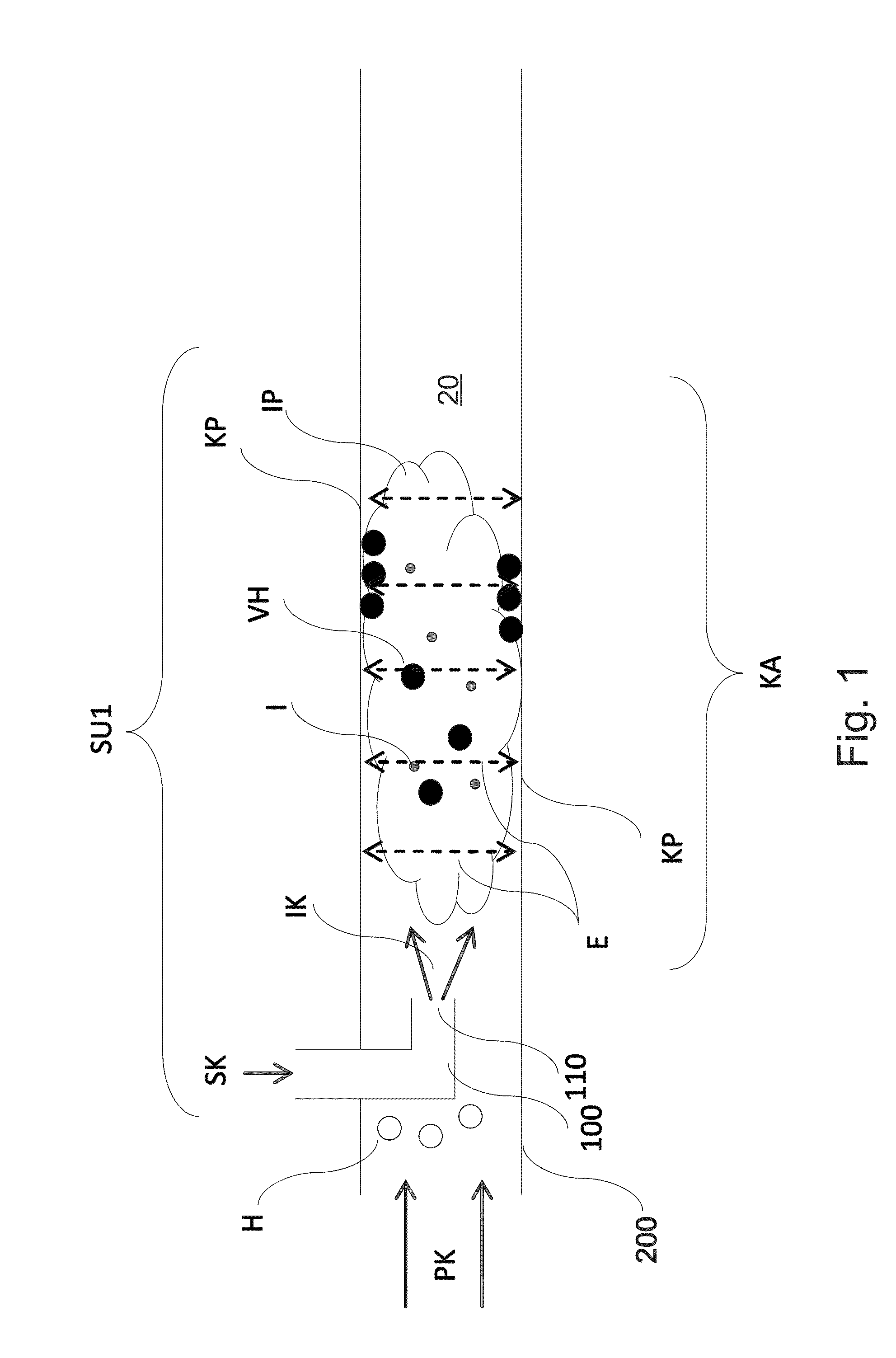
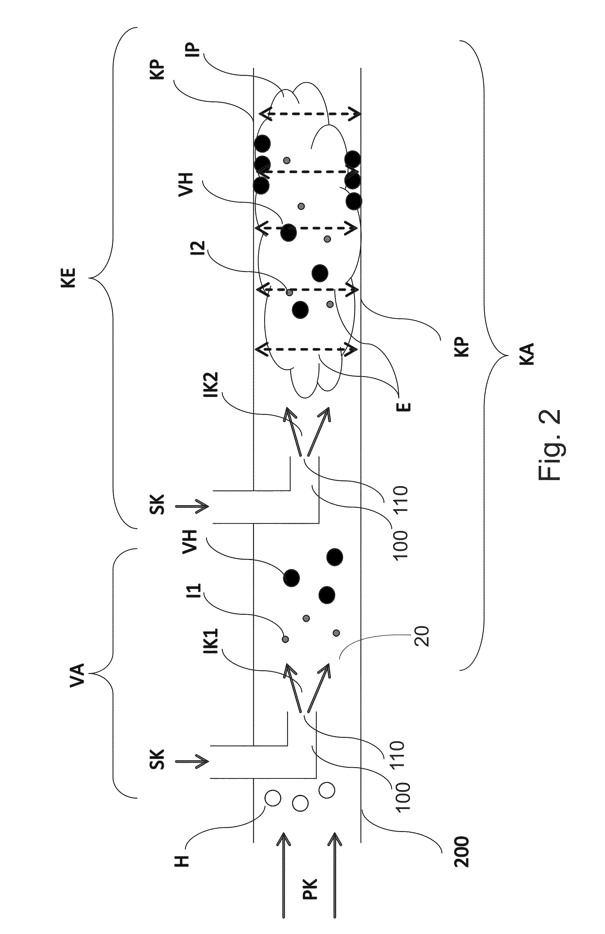
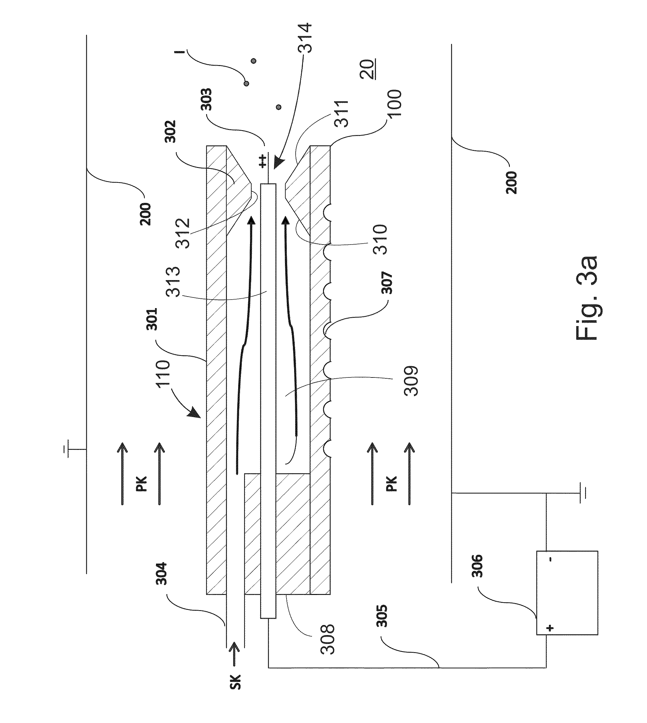
[0053]For reasons of clarity, the figures only show the details necessary in terms of the invention. Structures and details that are unnecessary in terms of the invention, but which will be obvious to one skilled in the art, have been omitted from the figures, in order to emphasize the specific features of the invention. Such unnecessary details are, among others, the firebox and the more detailed structures of the heat exchanger.

[0054]In the method according to the invention, a flue gas containing fine particles, which can come from, for example, a boiler, is cleaned of fine particles by collecting the fine particles on collector surfaces. In the method, for example, the flue gases containing fine particles exiting the combustion chamber are led to a selected chamber acting as a flow channel delimited by walls, such as, for example, a flow channel flowing downwards from the boiler. An ion source separate from the selected chamber delimited by walls is situated in the flow channel a...


PUM


Abstract

A method for collecting fine particles from flue gases onto selected collector surfaces includes leading the flue gases from a combustion chamber to a selected chamber that is part of a flow channel of the flue gasses. The selected channel is delimited by walls presenting the selected collector surfaces. Gas ions are formed with aid of a corona discharge of an ion source inside the selected chamber. The ion source includes a separate body relative to the selected chamber that is electrically passive and contains a corona electrode maintained at a high-voltage relative to the collector surfaces. The selected collector surfaces form a counter potential to the high voltage of the corona electrode. The gas ions are led to the selected chamber and mixed with the flue gases to charge the fine particles in the flue gas which are collected on the selected collector surfaces.

Description

BACKGROUND OF THE INVENTION[0001]The present invention relates to a method for collecting fine particles from flue gases onto selected collector surfaces, in which method[0002]flue gases containing fine particles exiting from a combustion chamber are led to a selected chamber delimited by walls, which is part of the flow channel of the flue gas,[0003]with the aid of a corona discharge of a corona electrode which is in high-voltage relative to the collector surfaces of an ion source, gas ions are formed in a separate body relative to the chamber, the ion source being inside the body,[0004]the gas ions formed are led to the selected chamber delimited by walls and mixed with the flue gases in order to charge the fine particles contained in the flue gas with the aid of gas ions, and[0005]the charged fine particles are collected on collector surfaces.[0006]The invention also relates to a corresponding device and arrangement.[0007]Aerosol fine particles, i.e. particles floating in a gas, ...

Claims


Application Information

Patent Timeline
Patent Type & Authority Applications(United States)
IPC IPC(8): F23J15/02B03C3/45B03C3/74B03C3/41
CPCF23J15/022B03C3/743B03C3/45B03C3/41B03C3/12B03C3/06B03C3/49B03C2201/08B03C2201/30F23J2217/102B03C3/38B03C3/82F23J15/00
Inventor LAITINEN, ARIRAIHA, MIKAPAAVILAINEN, SEPPOKESKINEN, JORMA
Owner TASSU ESP
Why Eureka
Try Eureka