
Pressure sensing assembly

a technology of pressure sensing and assembly, which is applied in the direction of converting sensor output, surveying, instruments, etc., can solve the problems of tube wall diameter change, tube wall axial curvature change,

Inactive Publication Date: 2015-08-13
NEDERLANDSE ORG VOOR TOEGEPAST-NATUURWETENSCHAPPELIJK ONDERZOEK (TNO)
View PDF10 Cites 12 Cited by
  • Summary
  • Abstract
  • Description
  • Claims
  • Application Information

AI Technical Summary

Benefits of technology

The present invention provides a pressure sensing assembly that enables continuous, real-time monitoring of pressure and temperature distribution in an oil or gas well. The assembly can include a single sensor unit or multiple sensor units axially spaced apart. The tube wall fixation devices of the sensor units can be rigidly connected to each other to prevent axial elongations due to external forces. The strain sensing elements can be connected to the tube wall fixation devices using electrical wiring or optical fiber. The technical effect is that the assembly accurately measures pressure and temperature distribution in real-time, which is useful for monitoring the performance and safety of oil and gas wells.

Problems solved by technology

Secondly, the tube wall fixation devices ensure that a local deformation of the tube wall due to a local pressure differential across the tube wall at a point in between the two tube wall fixation devices results in a change in axial curvature (i.e. curvature in an axial plane) of the tube wall that corresponds to an axial elongation.
Without the tube wall fixation devices, the local pressure differential-induced deformation of the tube wall might merely result in a change in the tube wall diameter.

Method used


Image

  • Pressure sensing assembly
  • Pressure sensing assembly
  • Pressure sensing assembly

Examples


Embodiment Construction

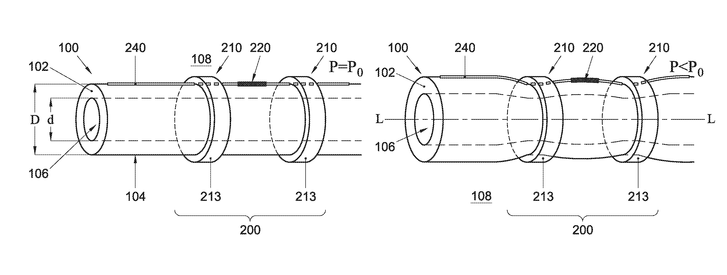
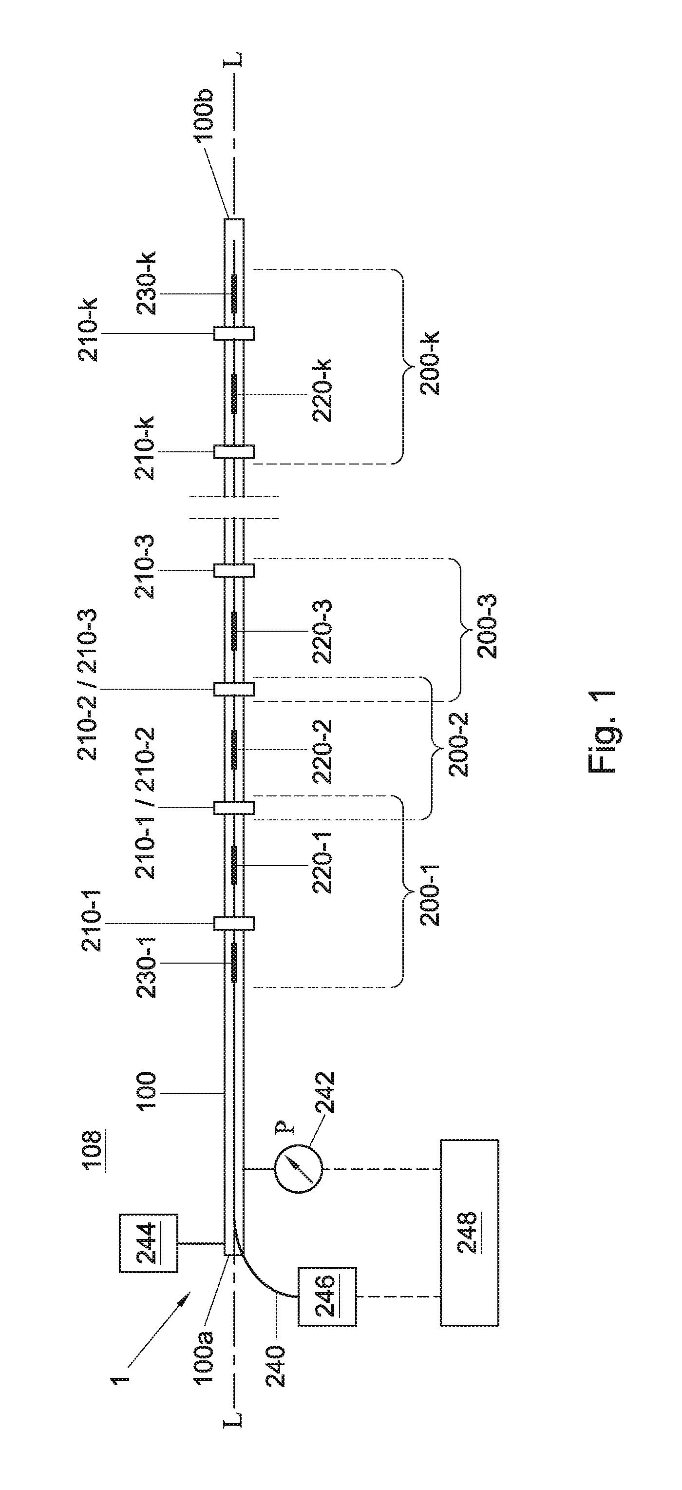
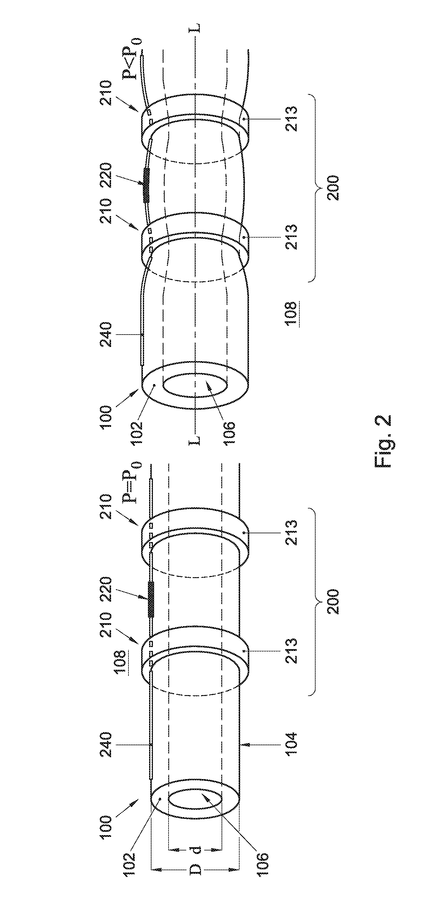
[0024]FIG. 1 schematically illustrates an exemplary pressure sensing assembly 1 according to the present invention, including an elongate tube 100 along which a plurality of sensor units 200-1, 200-2, 200-k are provided. FIG. 2 shows two schematic perspective views of a longitudinal portion of the tube 100 including one such sensor unit 200 in more detail; the left and right perspective views illustrate the tube 100 in an undeformed and a deformed state, respectively. FIGS. 3-5 schematically illustrate alternative embodiments of a sensor unit 200 according to the present invention. Below the construction and operation of the pressure sensing assembly 1 according to the present invention will be expounded in general terms, and with reference to FIGS. 1-5 where applicable.

[0025]Referring now to in particular FIGS. 1 and 2. The tube 100 of the pressure sensing assembly 1 may extend along an axis L between a first end 100a and a second, opposite end 100b, and have a flexible, preferably...


PUM


Abstract

A pressure sensing assembly (1), comprising: an elongate, axially extending tube (100), having a flexible tube wall (102) that encloses an inner pressure chamber (106); and at least one sensor unit (200), including: two tube wall fixation devices (210), connected to the tube wall (102) at respective axially spaced apart positions, and configured to fix respective diameters (D, d) of the tube wall at said positions; and a first strain sensing element (220), connected to the tube wall (102) at a first position axially in between said two tube wall devices (210), and configured to provide a first signal indicative of an axial elongation of the tube wall resulting from a change in axial curvature of the tube wall when a pressure differential between the inner pressure chamber (106) and an outside environment (108) of the tube is applied across the tube wall at said first position.

Description

FIELD OF THE INVENTION[0001]The present invention relates to a pressure sensing assembly suitable for continuously monitoring a pressure distribution down a borehole of an oil or gas well.BACKGROUND[0002]For an optimal economic and safe exploitation of a large and complex oil or gas well, it is highly desirable to have the disposal of fluid pressure and fluid temperature data from multiple vertically spaced apart locations within the well's borehole(s). Such pressure and temperature data may, for instance, provide information about which sections of a well produce hydrocarbons, reduce uncertainty in reservoir modelling, optimize placement of new wellheads, promote production by enabling the use of electrical submersible pumps (ESPs) to be tailored to the well-specific situation, and allow for careful well surveillance (e.g. the detection of possibly dangerous gas leaks).[0003]Presently, local pressure and temperature measurements are typically performed using single-point electric o...

Claims


Application Information

Patent Timeline
IPC IPC(8): G01L7/04G01L1/24E21B47/06
CPCG01L7/041G01L1/246E21B47/06G01L9/0027G01L11/025G01D5/35316G01D5/35387
Inventor CHENG, LUN KAITOET, PETER MARTIJNJANSEN, RIK
Owner NEDERLANDSE ORG VOOR TOEGEPAST-NATUURWETENSCHAPPELIJK ONDERZOEK (TNO)
Learn More