Optical member, polarizing plate set, and liquid crystal display device

Inactive Publication Date: 2015-08-13
NITTO DENKO CORP
View PDF7 Cites 20 Cited by
  • Summary
  • Abstract
  • Description
  • Claims
  • Application Information

AI Technical Summary

Benefits of technology

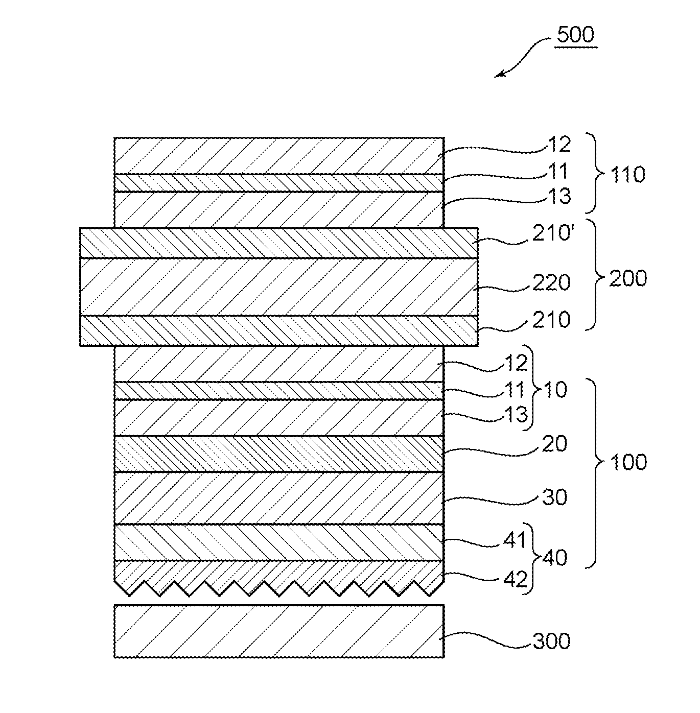
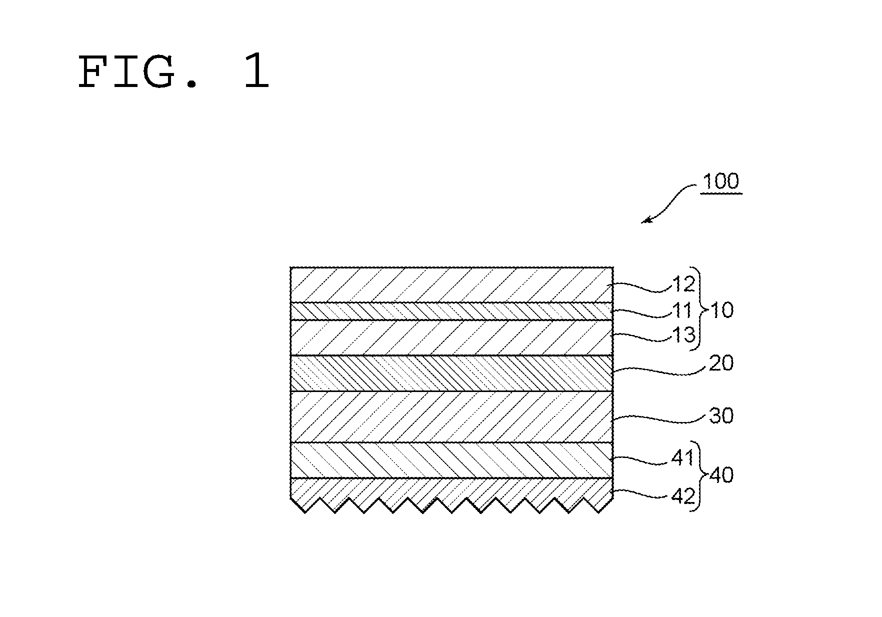
[0014]According to an embodiment of the present invention, in the optical member including the polarizing plate, the light-diffusing pressure-sensitive adhesive layer, the reflective polarizer, and the prism sheet, the volume-average particle diameter of the light-diffusible fine particles in the light-diffusing pressure-sensitive adhesive layer and the refractive index of the pressure-sensitive adhesive in the light-diffu

Problems solved by technology

In a liquid crystal display apparatus using such a surface light source device as described above, the prism sheet and the light guide plate are rubbed against each other when installing the prism sheet or under an actual usage environment, and the light guide plate is flawed in some cases.
However, a liquid crystal display apparatus using such polarizing plate with which the prism sheet is integrated has a problem of being dark because front brightness is insufficient.
Further, a liquid crystal display apparatus using such surface light source device as described above involves a problem in that moire occurs owing to the regular structure of the prism sheet.
However, the use of a light diffusio

Method used


Image

  • Optical member, polarizing plate set, and liquid crystal display device
  • Optical member, polarizing plate set, and liquid crystal display device
  • Optical member, polarizing plate set, and liquid crystal display device

Examples


example 1

Production of Film for First Retardation Layer

[0124]A commercially available polymer film [manufactured by Optes Inc., trade name: “ZeonorFilm ZF14-130 (thickness: 60 μm, glass transition temperature: 136° C.)”] whose main component was a cyclic polyolefin-based polymer was subjected to fixed-end uniaxial stretching in its width direction with a tenter stretching machine at a temperature of 158° C. in such a manner that its film width was 3.0 times as large as the original film width (lateral stretching step). The resultant film was a negative biaxial plate (three-dimensional refractive index: nx>ny>nz) having a fast axis in the conveying direction. The negative biaxial plate had an in-plane retardation of 118 nm and an Nz coefficient of 1.16.

[0125](Production of Film for Second Retardation Layer)

[0126]A pellet-shaped resin of a styrene-maleic anhydride copolymer (manufactured by Nova Chemicals Japan Ltd., product name: “DYLARK D232”) was extruded with a single screw extruder and a ...

example 2

[0141]A liquid crystal display apparatus was produced in the same manner as in Example 1 except that the light-diffusible fine particles in the light-diffusing pressure-sensitive adhesive composition were changed to TOSPEARL 120 manufactured by Momentive Performance Materials Inc. (particle diameter: 2 μm). The resultant liquid crystal display apparatus was subjected to the evaluations (1) to (5). Table 1 shows the results.

example 3

[0142]A liquid crystal display apparatus was produced in the same manner as in Example 1 except that the light-diffusible fine particles in the light-diffusing pressure-sensitive adhesive composition were changed to TOSPEARL 145 manufactured by Momentive Performance Materials Inc. (particle diameter: 4 μm). The resultant liquid crystal display apparatus was subjected to the evaluations (1) to (5). Table 1 shows the results.


PUM


Abstract

There is provided an optical member that suppresses the occurrence of moire and glare, and can realize a liquid crystal display apparatus that is excellent in mechanical strength and has high brightness. An optical member according to an embodiment of the present invention includes: a polarizing plate; a light-diffusing pressure-sensitive adhesive layer; a reflective polarizer; and a prism sheet. A volume-average particle diameter of light-diffusible fine particles in the light-diffusing pressure-sensitive adhesive layer is from 1 μm to 4 μm; and a refractive index of a pressure-sensitive adhesive in the light-diffusing pressure-sensitive adhesive layer is 1.47 or more.

Description

TECHNICAL FIELD[0001]The present invention relates to an optical member, a polarizing plate set, and a liquid crystal display apparatus. More specifically, the present invention relates to an optical member including a polarizing plate, a light-diffusing pressure-sensitive adhesive layer, a reflective polarizer, and a prism sheet, and a polarizing plate set and a liquid crystal display apparatus each using the optical member.BACKGROUND ART[0002]In recent years, as a display, a liquid crystal display apparatus using a surface light source device has been remarkably widespread. In a liquid crystal display apparatus including an edge light-type surface light source device, for example, light emitted from a light source enters a light guide plate, and propagates through an inside of the light guide plate while repeating a total reflection on a light output surface (liquid crystal cell-side surface) of the light guide plate and a back surface thereof. A part of the light that propagates ...

Claims


Application Information

Patent Timeline
IPC IPC(8): G02F1/1335G02B5/30G02B5/02
CPCG02F1/133504G02B5/0242G02F2001/133507G02B5/3025G02F1/133536G02B5/0231G02B5/0278G02B5/30G02F1/133528G02F1/133606G02F1/13362G02B5/0289G02B5/305G02F1/133607G02F1/133507
Inventor FUCHIDA, TAKEHITOMAEZAWA, SHOUHEINAKAMURA, KOZOTAKEMOTO, HIROYUKIMURAKAMI, NAO
Owner NITTO DENKO CORP
Why Eureka
Try Eureka