
Silicon on insulator device with partially recessed gate

a technology of silicon on insulator and gate, which is applied in the direction of semiconductor devices, basic electric elements, electrical appliances, etc., can solve the problems of premature transistor on, device turning, and difficulty in maintaining precise control of various electrical characteristics of semiconductor devices, so as to reduce short channel effects, improve transistor performance, and facilitate control transistor performan

Active Publication Date: 2015-08-13
STMICROELECTRONICS SRL
View PDF14 Cites 10 Cited by
  • Summary
  • Abstract
  • Description
  • Claims
  • Application Information

AI Technical Summary

Benefits of technology

This patent describes a method for making transistors on a silicon-on-insulator semiconductor wafer. By using a buried oxide layer shaping the dopant profiles, and partially recessing the gate, the transistor performance can be improved and short channel effects such as drain-induced barrier lowering and sub-threshold slope can be reduced. The depth of the gate recess can be adjusted to place the channel at different depths, and advanced process control can be used to guide the formation of the recess in accordance with the dopant profiles.

Problems solved by technology

As technology nodes for integrated circuits scale below 10 nm, maintaining precise control of various electrical characteristics in semiconductor devices becomes increasingly more challenging.
However, when the channel length between the doped source and drain regions is reduced so far as to be comparable to their depth, current may leak through such a short channel, causing the device to turn on at an applied voltage that is less than the threshold voltage.
DIBL occurs when a high drain voltage causes the transistor to turn on prematurely, even though the Vt electric potential barrier has not been overcome.
However, strained silicon and other new technologies fail to address all of the technology challenges listed above.

Method used


Image

  • Silicon on insulator device with partially recessed gate
  • Silicon on insulator device with partially recessed gate
  • Silicon on insulator device with partially recessed gate

Examples


Embodiment Construction

[0023]In the following description, certain specific details are set forth in order to provide a thorough understanding of various aspects of the disclosed subject matter. However, the disclosed subject matter may be practiced without these specific details. In some instances, well-known structures and methods of semiconductor processing comprising embodiments of the subject matter disclosed herein have not been described in detail to avoid obscuring the descriptions of other aspects of the present disclosure.

[0024]Unless the context requires otherwise, throughout the specification and claims that follow, the word “comprise” and variations thereof, such as “comprises” and “comprising” are to be construed in an open, inclusive sense, that is, as “including, but not limited to.”

[0025]Reference throughout the specification to “one embodiment” or “an embodiment” means that a particular feature, structure, or characteristic described in connection with the embodiment is included in at le...


PUM


Abstract

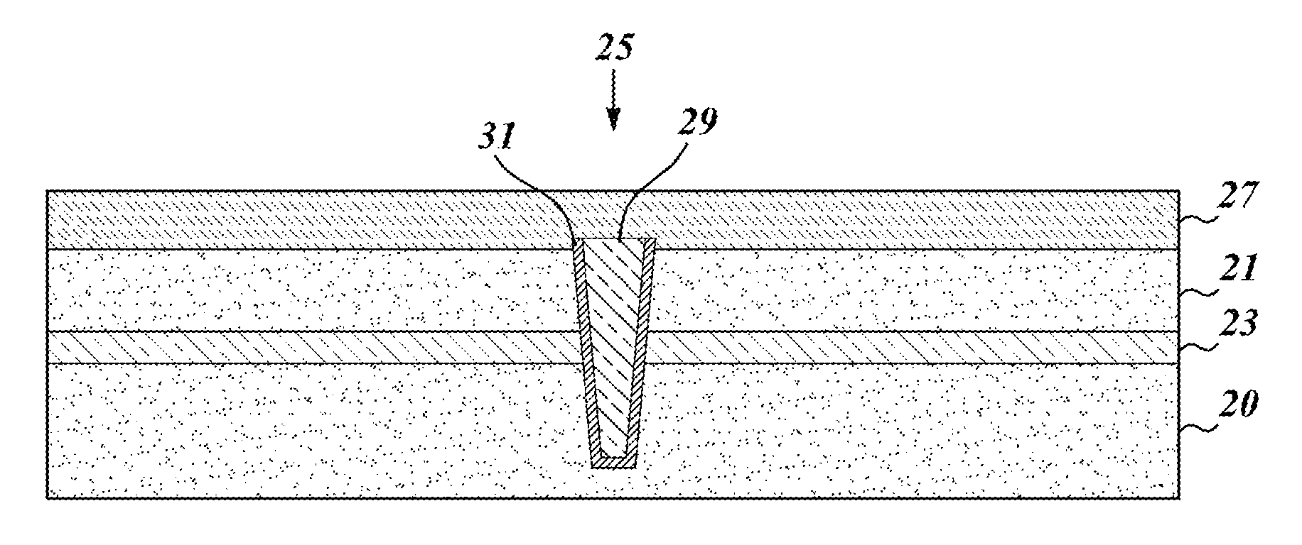
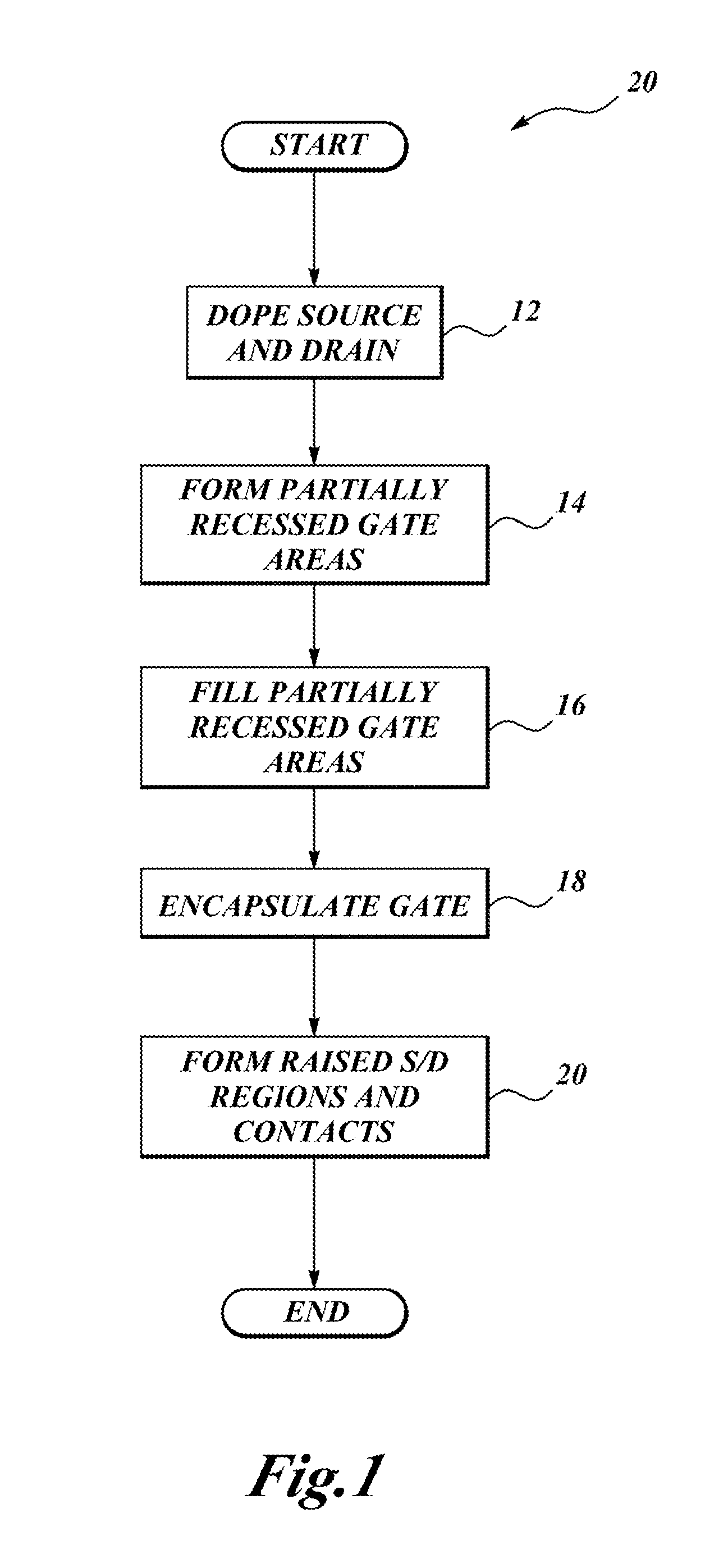
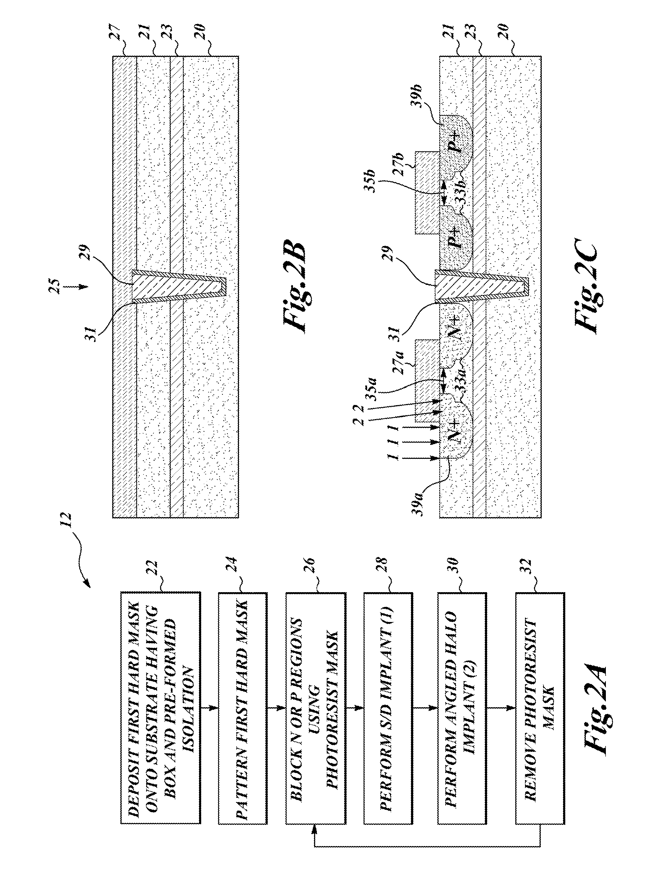
Transistors having partially recessed gates are constructed on silicon-on-insulator (SOI) semiconductor wafers provided with a buried oxide layer (BOX), for example, FD-SOI and UTBB devices. An epitaxially grown channel region relaxes constraints on the design of doped source and drain profiles. Formation of a partially recessed gate and raised epitaxial source and drain regions allow further improvements in transistor performance and reduction of short channel effects such as drain induced barrier lowering (DIBL) and control of a characteristic subthreshold slope. Gate recess can be varied to place the channel at different depths relative to the dopant profile, assisted by advanced process control. The partially recessed gate has an associated high-k gate dielectric that is initially formed in contact with three sides of the gate. Subsequent removal of the high-k sidewalls and substitution of a lower-k silicon nitride encapsulant lowers capacitance between the gate and the source and drain regions.

Description

BACKGROUND[0001]1. Technical Field[0002]The present disclosure relates to the fabrication of nanometer-sized integrated circuit field-effect transistor (FET) devices and, in particular, to devices that incorporate a buried oxide layer and a partially recessed transistor gate to control electrical characteristics of the devices.[0003]2. Description of the Related Art[0004]As technology nodes for integrated circuits scale below 10 nm, maintaining precise control of various electrical characteristics in semiconductor devices becomes increasingly more challenging. Such semiconductor devices include, for example, metal-oxide-semiconductor field-effect transistors (MOSFETs). A MOSFET is a three-terminal switching device that includes a source, a gate, and a drain. MOSFETs are interconnected by a network of wires through contacts to each of the source, drain, and gate terminals.[0005]When a voltage exceeding a selected threshold voltage (Vt) is applied to the MOSFET gate, the device switch...

Claims


Application Information

Patent Timeline
Patent Type & Authority Applications(United States)
IPC IPC(8): H01L29/78H01L29/66
CPCH01L29/66477H01L29/78H01L21/823807H01L21/823828H01L29/1054H01L29/66545H01L29/66583H01L29/66621H01L29/66651H01L29/66636H01L29/7848H01L29/165H01L29/66772H01L29/78684H01L29/78696
Inventor ZHANG, JOHN H.
Owner STMICROELECTRONICS SRL
Learn More