
Coiled anchor for supporting prosthetic heart valve, prosthetic heart valve, and deployment device

a technology of prosthetic heart valves and coiled anchors, which is applied in the field of prosthetic heart valve replacement, can solve the problems of eversion of the leaflets of the mitral valve back into the atrium, death of the heart, and prolapse of the mitral valve leaflet, and achieves little or no effective commercially available ways to replace the mitral valv

Active Publication Date: 2015-08-20
MITRAL VALVE TECHNOLOGIES SARL
View PDF13 Cites 151 Cited by
  • Summary
  • Abstract
  • Description
  • Claims
  • Application Information

AI Technical Summary

Benefits of technology

The invention is a device and method for replacing a mitral valve. The device helps anchor the replacement valve in place and prevents blood leakage around it. It can be used in various procedures and can interact with the native valve and heart better. The method of replacing the valve allows for flexibility in the procedure, with different options for positioning and deploying the replacement valve. Overall, the invention makes the replacement of mitral valves easier and safer.

Problems solved by technology

Due to the large pressure differential between the left ventricle and the left atrium during ventricular contraction, a possibility of prolapse, or eversion of the leaflets of the mitral valve back into the atrium, arises.
Complications of the mitral valve can potentially cause fatal heart failure.
There are little or no effective commercially available ways to replace a mitral valve through catheter implantation and / or other minimal or less invasive procedures.
This discrepancy stems from replacement of a mitral valve being more difficult than aortic valve replacement in many respects, for example, due to the physical structure of the valve and more difficult access to the valve.
The most prominent obstacle for mitral valve replacement is anchoring or retaining the valve in position, due to the valve being subject to a large cyclic load.
Also, the movement and rhythmic load can fatigue materials, leading to fractures of the implanted valve.
If the orientation of a mitral prosthesis is unintentionally shifted, blood flow between the left atrium and the left ventricle may be obstructed or otherwise negatively affected.
While puncturing the tissue in or around the mitral valve annulus to better anchor an implanted valve is an option for retaining the placement of the implant, this may potentially lead to unintended perforation of the heart and patient injury.
Referring back to FIG. 2, another issue with mitral valve replacement is the size and shape of the native mitral valve.
As such, a circular mitral valve implant that is too small may cause leaks around the implanted valve (i.e., paravalvular leak) if a good seal is not established around the valve.
Meanwhile, a circular valve implant that is too large may stretch out and damage the valve annulus.
However, these additions may restrict valve delivery through a catheter and / or minimally invasive procedures, since the additional fabric may be difficult to compress and deploy through a catheter.

Method used


Image

  • Coiled anchor for supporting prosthetic heart valve, prosthetic heart valve, and deployment device
  • Coiled anchor for supporting prosthetic heart valve, prosthetic heart valve, and deployment device
  • Coiled anchor for supporting prosthetic heart valve, prosthetic heart valve, and deployment device

Examples


Embodiment Construction

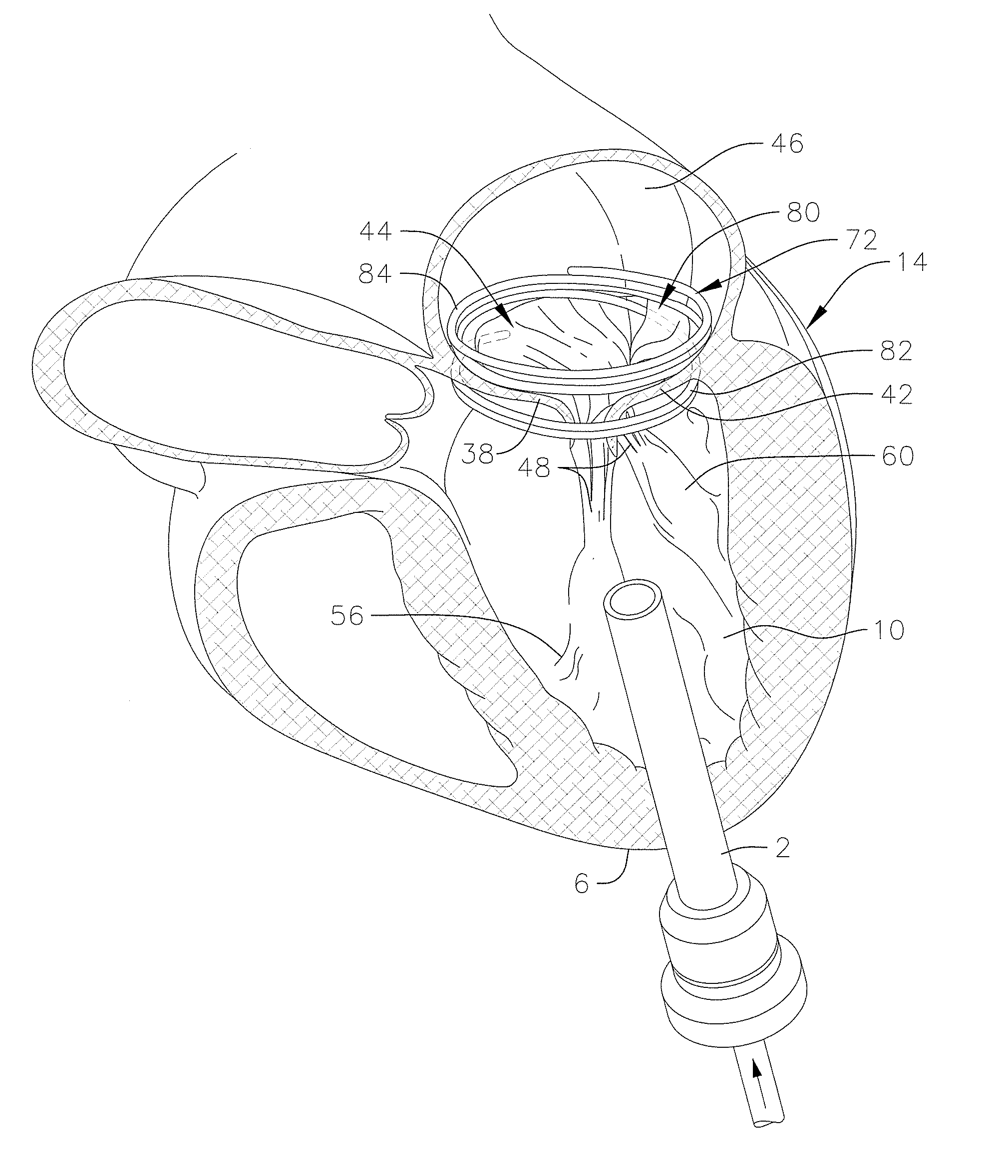
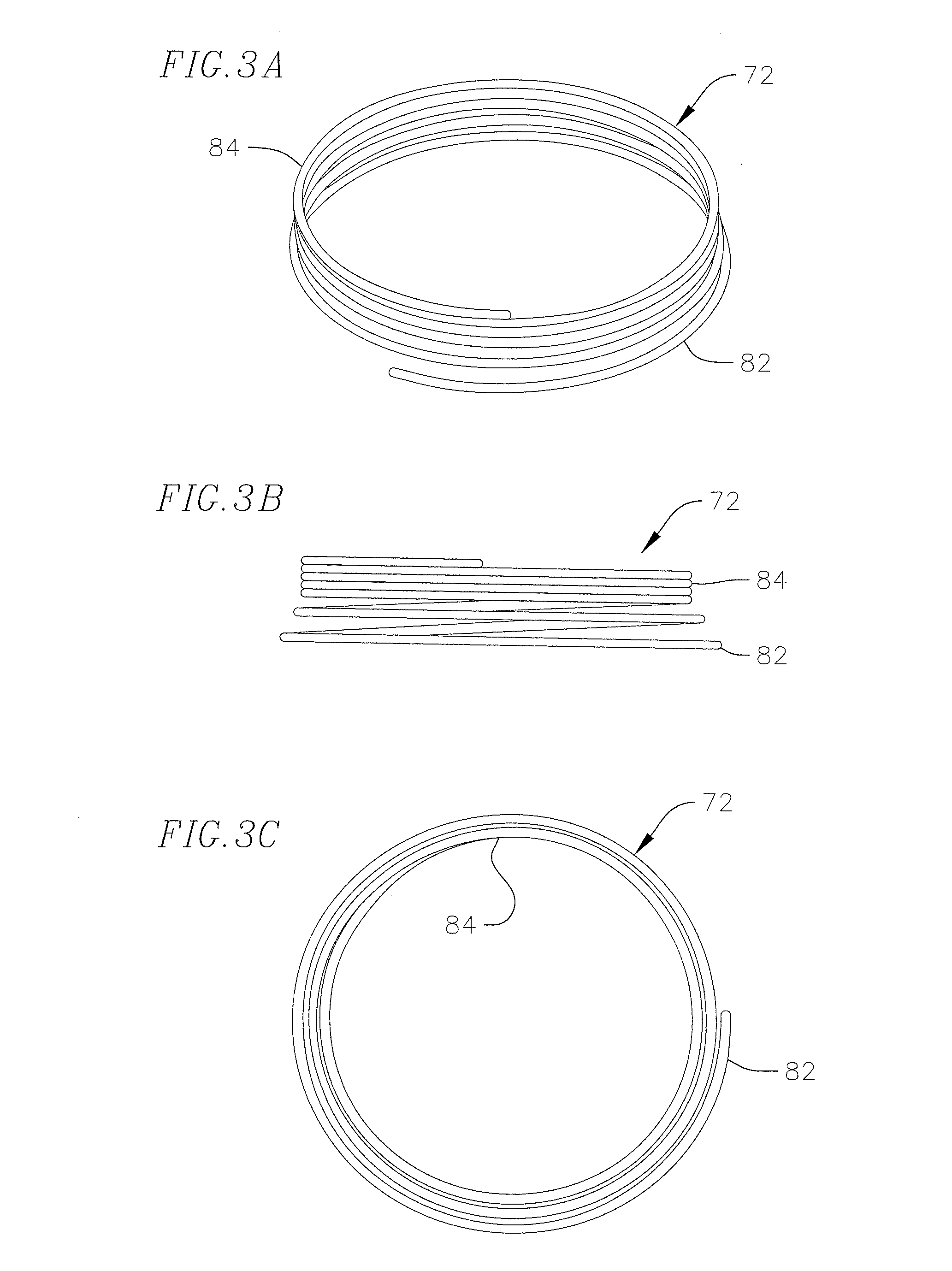
[0032]A helical anchor according to an embodiment of the invention is constructed as seen in FIGS. 3A to 3E. FIG. 3A shows a perspective view of a helical anchor 72, FIG. 3B shows a side view of the anchor 72, and FIG. 3C shows a top view of the anchor 72. The helical anchor 72 includes a coil with a plurality of turns extending along a central axis of the anchor. The anchor 72 has a series of lower turns or coils 82 and a series of upper turns or coils 84. The individual turns of the lower coils 82 are spaced apart from one another by small gaps. Meanwhile, the individual turns of the upper coils 84 are wound more closely to one another. In addition, the turns of the lower coils 82 have a larger radius of curvature than the turns of the upper coils 84, and therefore form a larger inner annular space. These features will be discussed in more detail below with respect to implantation of the anchor 72 at a native mitral valve. In other embodiments, the characteristics and differences ...


PUM


Abstract

A coiled anchor for docking a mitral valve prosthesis at a native mitral valve of a heart has a first end, a second end, and a central axis extending between the first and second ends, and defines an inner space coaxial with the central axis. The coiled anchor includes a coiled core including a bio-compatible metal or metal alloy and having a plurality of turns extending around the central axis in a first position, and a cover layer around the core, the cover layer including a bio-compatible material that is less rigid than the metal or metal alloy of the coiled core.

Description

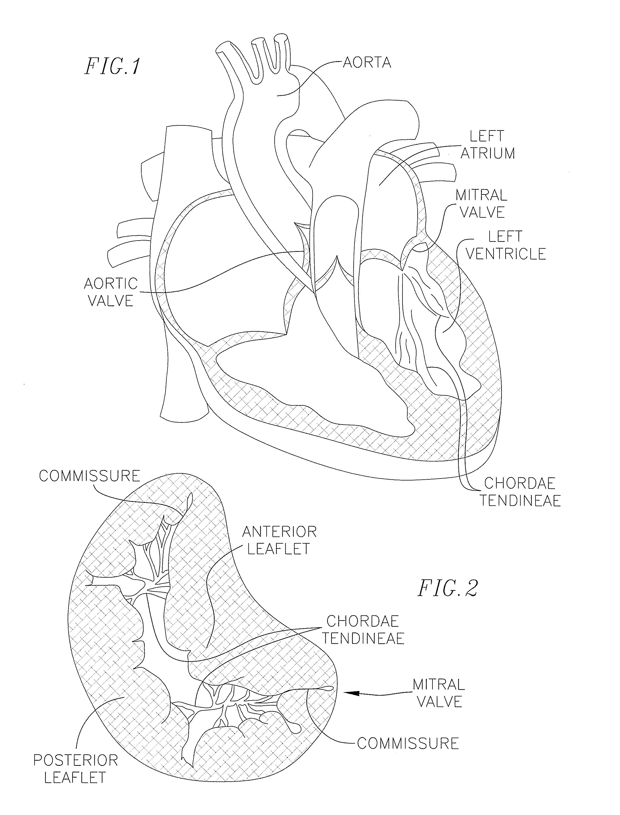
CROSS-REFERENCE TO RELATED APPLICATION(S)[0001]The present application claims priority to and the benefit of U.S. Provisional Patent Application Ser. No. 61 / 942,300, filed Feb. 20, 2014, the contents of which are hereby incorporated by reference in their entirety.BACKGROUND FIELD[0002]The invention generally relates to medical devices and procedures pertaining to prosthetic heart valves. More specifically, the invention relates to replacement of heart valves that may have malformations and / or dysfunctions. Embodiments of the invention relate to a prosthetic heart valve for replacing a mitral valve in the heart, an anchor to facilitate and maintain a positioning of the prosthetic heart valve in the native valve, and deployment devices and procedures associated with implantation of the prosthetic heart valve.DESCRIPTION OF RELATED ART[0003]Referring first generally to FIGS. 1 and 2, the mitral valve controls the flow of blood between the left atrium and the left ventricle of the human...

Claims


Application Information

Patent Timeline
IPC IPC(8): A61F2/24
CPCA61F2/2418A61F2/243A61F2210/0014A61F2230/0091A61F2210/0076A61F2250/0063
Inventor CHAU, MARKSIEGEL, ALEXANDER J.
Owner MITRAL VALVE TECHNOLOGIES SARL
Learn More