Cardiac Access Catheter, System, and Method

a catheter and access technology, applied in the field of medical devices, can solve the problems of difficult or impossible access, difficult or impossible navigation to access the desired anatomical location, and expensive or complicated equipment and procedures, and achieve the effects of improving delivery, superior approach, and improving alignment with the axis

Inactive Publication Date: 2015-08-27
JENSON MARK LYNN +3
View PDF4 Cites 102 Cited by
  • Summary
  • Abstract
  • Description
  • Claims
  • Application Information

AI Technical Summary

Benefits of technology

[0020]In one example, the present invention comprises a system for accessing a desired location in the heart from a transvenous route. For example, a percutaneous femoral vein access can be used, a catheter of the present invention is advanced cranially via the inferior vena cava and positioned so that a stabilizing element is secured at or near the right atrium. Alignment elements direct a directional element towards a desired location such as the coronary sinus ostium. The present invention may include alignment adjustment features which provide controlled movement of the directional element with respect to the stabilizing element, to provide for directing the directional element towards a desired axial distance and rotational orientation with respect to the stabilizing element. The stabilizing element can be structured with an asymmetric shape such that the axis of the catheter or apparatus is not aligned with the axis of the stabilizing member; the catheter can thereby be held by the basket into a position adjacent one wall of the vascular structure for improved advancement of the directional catheter across the vascular structure with better force transmission and location.
[0037]The present apparatus allows an improved delivery of a stiff and large TMVR catheter across the septum via an access from the superior vena cava. Such an access across the septum from a superior approach is currently not a preferred choice for the physician. However with the apparatus of the present invention, this superior approach is both reliable and allows improved alignment with the axis of the mitral annulus. The present invention first provides access to a first orifice that is more easily accessed from the superior approach such as the coronary sinus ostium. The position of the interatrial septum that is suitable for puncture and access from the right to the left atrium is positioned at a specific distance cranial from the coronary sinus. The septal puncture can be created at a specific angle that is generally at the same or similar angle as that used for access to the coronary sinus and with respect to the axis of the catheter of the present apparatus. The septal puncture made from the superior approach provides a more direct angle of approach to the mitral annulus without requiring the TMVR catheter to undergo significant bending. The TMVR catheter can then be in an improved alignment with the axis of the mitral valve. The septal puncture can be made without the potential for accidental puncture to neighboring vessels or cavities that could result in patient bleeding due to improper puncture of a neighboring vessel or death.

Problems solved by technology

Navigating to access the desired anatomical locations can be challenging, however.
Various guidewires, catheters, and imaging tools have been introduced to address these challenges, but access can still be difficult or impossible, or can require expensive or complicated equipment and procedures.
Vascular complications and other safety problems can occur, and access can be time-consuming.
Puncturing the interatrial septum in the wrong location can cause safety and effectiveness problems.
Incorrect puncture can cause hemorrhagic complications, with bleeding from the atrium into the extra-cardiac tissues and potential spaces, or could puncture the aorta, the esophagus, or other important tissues.
Even if the puncture is safe, positioning the puncture at a location that is in the wrong location or orientation can make it difficult or impossible to properly position a therapeutic device within the left atrium.
For example, trans-septal access originating from the inferior vena cava that is too far cranial, can make it difficult to guide a therapy device to the mitral valve and maintain any required alignment with the axis of the mitral valve.

Method used


Image

  • Cardiac Access Catheter, System, and Method
  • Cardiac Access Catheter, System, and Method
  • Cardiac Access Catheter, System, and Method

Examples


Embodiment Construction

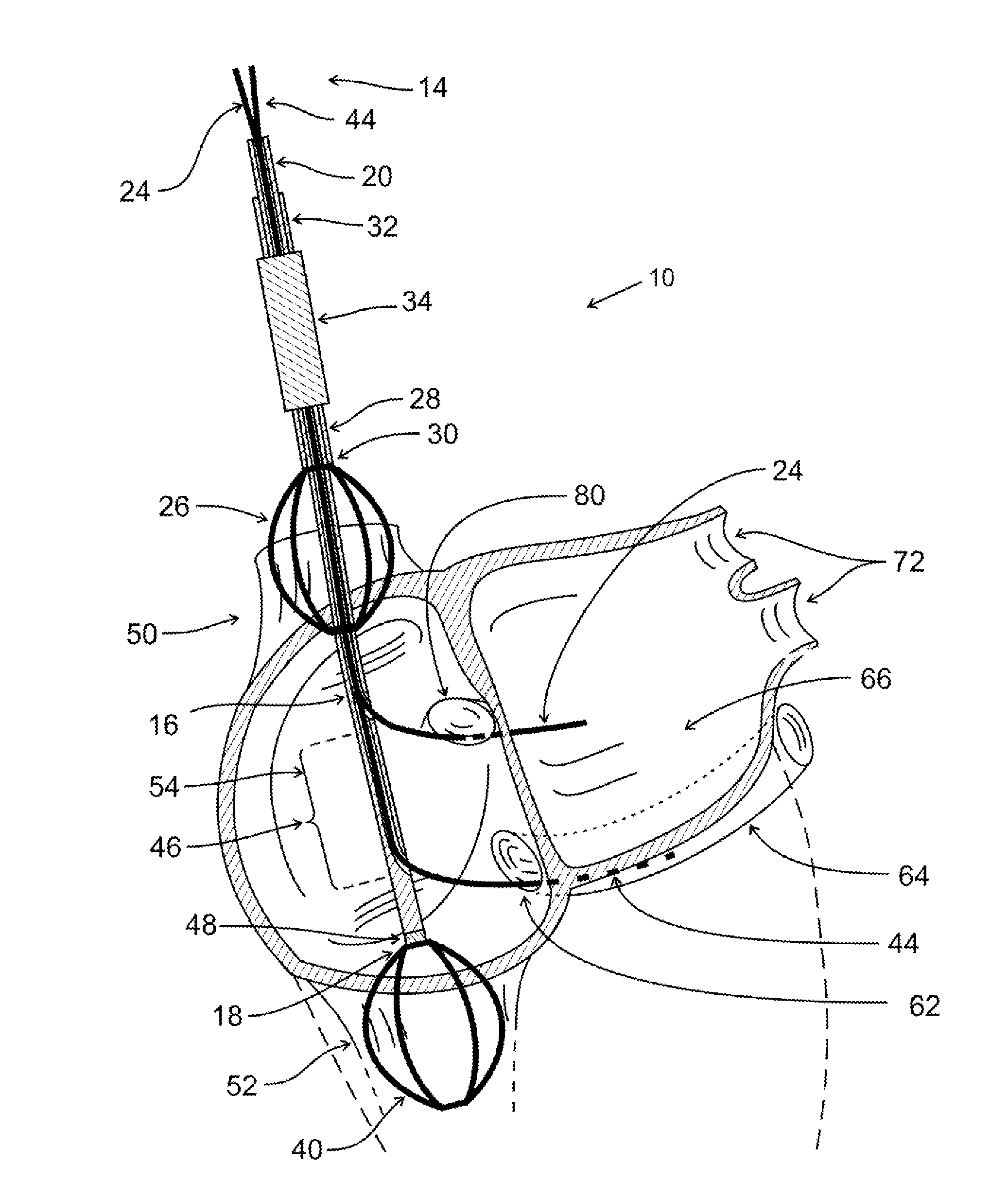
[0054]It is desired to direct a device to specific tissues and locations within the body to facilitate diagnosis, monitoring, treatment, or excision procedures in the body. While access to some tissues and locations is relatively simple, certain locations are difficult to access, with sufficient safety, ease, and reliability. This is especially true when it is desired to approach the tissues or locations in a less-invasive or minimally-invasive manner, as opposed to a more-invasive conventional surgical approach. For example, endoscopic, or catheter-based diagnosis and therapy, including percutaneous vascular approaches, are preferred when they can be performed safely and effectively.

[0055]It is particularly desirable to access portions of the heart and nearby structures from a percutaneous approach via a remote blood vessel. For example, it is desired to access left heart structures via transvenous routes, such as an inferior route from a femoral venous access, for example, or a su...


PUM


Abstract

A system for accessing a desired location in the heart or other target areas has an alignment catheter which directs a directional element towards a target area. A second directional element can be directed towards a target tissue, using the known location of the first directional element as a basis to easily locate other tissues and targets. One or more stabilization elements can help to stabilize the distal portion of the apparatus near the target area. The system can be used for transvenous access to the transatrial septum for transatrial access to the mitral valve, for example, and can use a stabilization basket near the right atrium. The system can be used for coronary sinus access or access to other targets. Various configurations are disclosed, as are various stabilization elements, directional elements, combinations, and methods.

Description

RELATED PATENT DOCUMENTS[0001]This patent application claims benefit from the earlier filed U.S. Provisional Application No. 61 / 966,478 filed Feb. 24, 2014 entitled “Cardiac Access Catheter, System, and Method”, pending, which is hereby incorporated into this application by reference as if fully set forth herein.BACKGROUND[0002]1. Field of the Invention[0003]The present invention pertains generally to medical devices, and particularly to medical devices for catheter-based treatments, and more particularly, for intravascular access to portions of the heart and associated vasculature.[0004]2. Description of the Prior Art[0005]Access to specific areas of the heart and associated vasculature is required for various catheter-based diagnostic and therapeutic procedures. In some situations, there is a need to intravascularly access the coronary sinus and associated structures such as the great cardiac vein and its branches. In other situations, there is a need to intravascularly access the...

Claims


Application Information

Patent Timeline
Patent Type & Authority Applications(United States)
IPC IPC(8): A61M25/01A61M25/09A61M25/00
CPCA61M25/0102A61M25/09A61M25/0043A61F2/95A61F2/86A61M25/04A61M25/0662A61M25/1002A61M25/1011A61M2025/0681A61M2025/1047A61M2025/1097A61M2210/125
Inventor JENSON, MARK LYNNDRASLER, WILLIAM JOSEPHKRAVIK, RICHARD C.DRASLER, II, WILLIAM JOSEPH
Owner JENSON MARK LYNN
Why Eureka
Try Eureka