Modular latent heat thermal energy storage systems

Active Publication Date: 2015-08-27
UCHICAGO ARGONNE LLC
View PDF10 Cites 26 Cited by
  • Summary
  • Abstract
  • Description
  • Claims
  • Application Information

AI Technical Summary

Benefits of technology

[0018]A further object of the present invention is to provide a modular energy storage system. A feature of the present invention is that the storage system is composed of a multitude of removable storage modules. An advantage of the present system is that individual modules can be replaced as necessary without disrupting the operation of the CSP plant.
[0019]Yet another object of the present invention is to provide a storage system that can easily accommodate cascaded latent heat storage media. A feature of the present invention is the use of a plurality of PCMs in one or a plurality of energy storage modules, each PCM having different melting temperatures. An advantage of the present invention is that the modules can be tailored such that the melting temperature of each PCM corresponds to the temperature of the HTF at that point in the storage module.
[0020]Still another object of the present invention is to provide a smaller and less expensive thermal energy storage system for power generating plants. A feature of the present invention is a single containerless storage design that encapsulates or otherwise comprises a plurality of modules. A further feature of the present invention is the ability to adjust the number of individual modules and the flow rate of the HTF through each of the modules. Advantages of the present invention include the reduction of capital installation costs by the single containerless storage design and the minimization of operational costs by t

Problems solved by technology

This mode of operation, however, only works while the sun is shining, and consequently, energy cannot be produced at night or on an overcast day (hereinafter referred to as “nonoptimal times”).
These storage tanks are large and expensive to fabricate.
Besides being large, the tanks are also difficult to maintain, requiring costly shutdown times to address even small

Method used


Image

  • Modular latent heat thermal energy storage systems
  • Modular latent heat thermal energy storage systems
  • Modular latent heat thermal energy storage systems

Examples


example 1

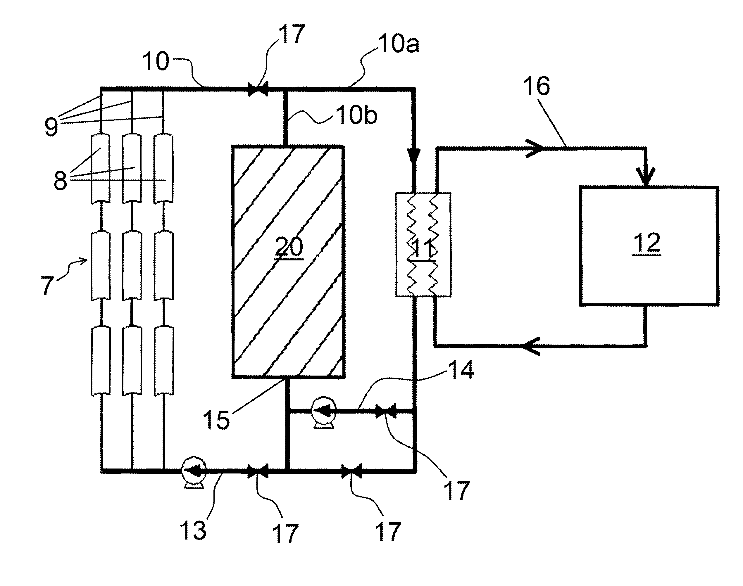
[0083]In this example, a 50-MW CSP plant with an eight-hour charging cycle and a twelve-hour discharging cycle is illustrated. The latent heat storage medium was magnesium chloride containing aligned ligament graphite foam as the thermal diffusion substrate. The PCM / foam combination had a thermal conductivity of about 30 W / mK and a foam porosity of about 90 percent, i.e., about 90 percent PCM and about 10 percent foam by volume. In an embodiment of the invention, most of the thermal conductivity is provided by the foam inasmuch as thermal conductivity of PCM alone is under approximately 0.5W / mK. The HTF conduits were fabricated from Inconel 617. The HTF was FLiNaK.

[0084]The size of the LHTES system varied according to an identified relationship between the HTF flow rate and the size of the HTF conduits. The inventors determined that a flow rate of 0.5 m / s and a NPS 8, SCH 10 HTF conduit (outside diameter of 219.08 mm; thickness of 3.759 mm) produced a system with the least capital ...

example 2

[0085]In this example, a 100-MW CSP plant with an eight-hour charging cycle and a twelve-hour discharging cycle will be considered. This LHTES system requires 4290 modules. The modules were spaced 0.54 m from center to center, which required a module cluster diameter of 34.6 m. Magnesium chloride supported on 90% porous aligned ligament graphite was used as the latent heat storage medium. The HTF was FLiNaK. The HTF pipes were Inconel 617 of size NPS 2, SCH 120. During charging, the HTF was set to a flow rate of 0.15 m / s. During discharging, the HTF was set to a flow rate of 0.1 m / s.

[0086]The following are temperature measurements for various components of the system. The latent heat storage medium had an initial temperature of 620° C. During charging the HTF had an inlet temperature of 820° C. and an outlet temperature of 765° C. The HTF remained above the PCM melt temperature along substantially the entire module length, and the temperature difference between the HTF and the PCM w...

example 3

[0088]In this example, the LHTES system featured the same specifications as that of Example 2 with the exception that the module 30 was cascaded. One method of fabricating a cascading module is to slide each preformed PCM / foam section over the HTF pipe in succession. The interface between two different PCM sections is not important because the heat transfer is in the radial, not axial, direction. The module was comprised of equal volumes of sodium chloride and magnesium chloride. The magnesium chloride was positioned downstream of the sodium chloride within the latent heat storage media 40. The sodium chloride section was in direct contact with the magnesium chloride section. The thermal diffusion substrate was aligned ligament graphite foam of 90% porosity. These changes resulted in slightly higher module outlet temperatures: 773° C. during charging and 665° C. during discharging.

[0089]The overall exergy efficiency of this system was calculated to be 97.8%. This example shows that ...


PUM


Abstract

The invention provides a modular device for latent heat storage, which is made of a conduit with a first end and a second end; and a jacket that surrounds a portion of the conduit between the first end and the second end, wherein the jacket is comprised of at least one phase change material. The invention further provides a system for latent heat storage, comprising a thermally insulated enclosure adapted to receive at least one modular latent heat storage device and a HTF, wherein the HTF flows from an upstream heat source into each of the first ends of the conduit and out of each of the second ends of the conduit comprising the at least one module to a downstream heat exchanger.

Description

BACKGROUND OF THE INVENTION[0001]1. Field of the invention[0002]This invention is directed to a system for energy storage, and more particularly this invention relates to a system for storing thermal energy generated by concentrated solar power (CSP).[0003]2. Background of the Invention[0004]Solar power from the sun provides an almost limitless source of free fuel. Power produced through solar energy is renewable and clean, i.e., does not require the burning of fossil fuels.[0005]Although photovoltaic panels have received a vast amount of attention, one emerging form of harnessing the sun's power is the CSP plant. CSP plants utilize fields of mirrors, called heliostats, to reflect the sun's rays to a focal point, called a receiver. Most heliostats are able to rotate or tilt to follow the sun throughout the day to maximize the amount of sunlight reflected. Further, a multitude of receivers have been developed to effectively distribute the energy to downstream components. For instance...

Claims


Application Information

Patent Timeline
IPC IPC(8): F28D20/02F24J2/34
CPCF28D20/021F24J2/34F28D20/026F28D20/023F03G6/067F28D2020/0013F28F13/00F28F2270/00Y02E10/46Y02E60/14
Inventor FRANCE, DAVID M.YU, WENHUASINGH, DILEEPKIM, TAEIL
Owner UCHICAGO ARGONNE LLC
Why Eureka
Try Eureka