
Method for Monitoring an Electrical Power Supply Line Comprised in a Seismic Cable, Corresponding System, Computer Program Product and Non-Transitory Computer-Readable Carrier Medium

a technology of electrical power supply line and seismic cable, which is applied in the direction of instruments, optical apparatus testing, structural/machine measurement, etc., can solve the problems of safety, seismic cable b>100/b> is open or damaged, and not only the overall weight and size of seismic cable, but also the size of connectors, so as to achieve simple and cost-effective implementation

Inactive Publication Date: 2015-08-27
SERCEL INC
View PDF12 Cites 3 Cited by
  • Summary
  • Abstract
  • Description
  • Claims
  • Application Information

AI Technical Summary

Benefits of technology

The invention is about monitoring the performance of an electrical power supply line in a seismic cable using an optical loop. The system uses the existing optical transmitter line to check the proper functioning of the power supply line, instead of requiring a dedicated electrical loop. This reduces the weight of the cable and makes maintenance easier. The system also detects the location of any failure in the power supply line, allowing for faster intervention and maintenance. The system uses optical connectors along the cable to continuously monitor the line and can easily locate the location of any defects.

Problems solved by technology

In marine seismic exploration, due to the length of the seismic cable, the controllers are supplied with high voltage from the seismic vessel (typically comprised between 300 and 900 V) via the electrical power supply line 50, which poses problems of safety.
If the impedance tends towards infinity, this means that the safety loop is open and so the seismic cable 100 is open or damaged.
However, this known solution has a number of drawbacks.
The use of a safety loop based on electrical impedance measurement requires two additional electrical copper lines per electrical power supply wire (a line electrical power supply line typically comprises a set of two electrical power supply wires), which has a significant impact on the overall weight and size of the seismic cable, but also on the size of the connectors.

Method used


Image

  • Method for Monitoring an Electrical Power Supply Line Comprised in a Seismic Cable, Corresponding System, Computer Program Product and Non-Transitory Computer-Readable Carrier Medium
  • Method for Monitoring an Electrical Power Supply Line Comprised in a Seismic Cable, Corresponding System, Computer Program Product and Non-Transitory Computer-Readable Carrier Medium
  • Method for Monitoring an Electrical Power Supply Line Comprised in a Seismic Cable, Corresponding System, Computer Program Product and Non-Transitory Computer-Readable Carrier Medium

Examples


Embodiment Construction

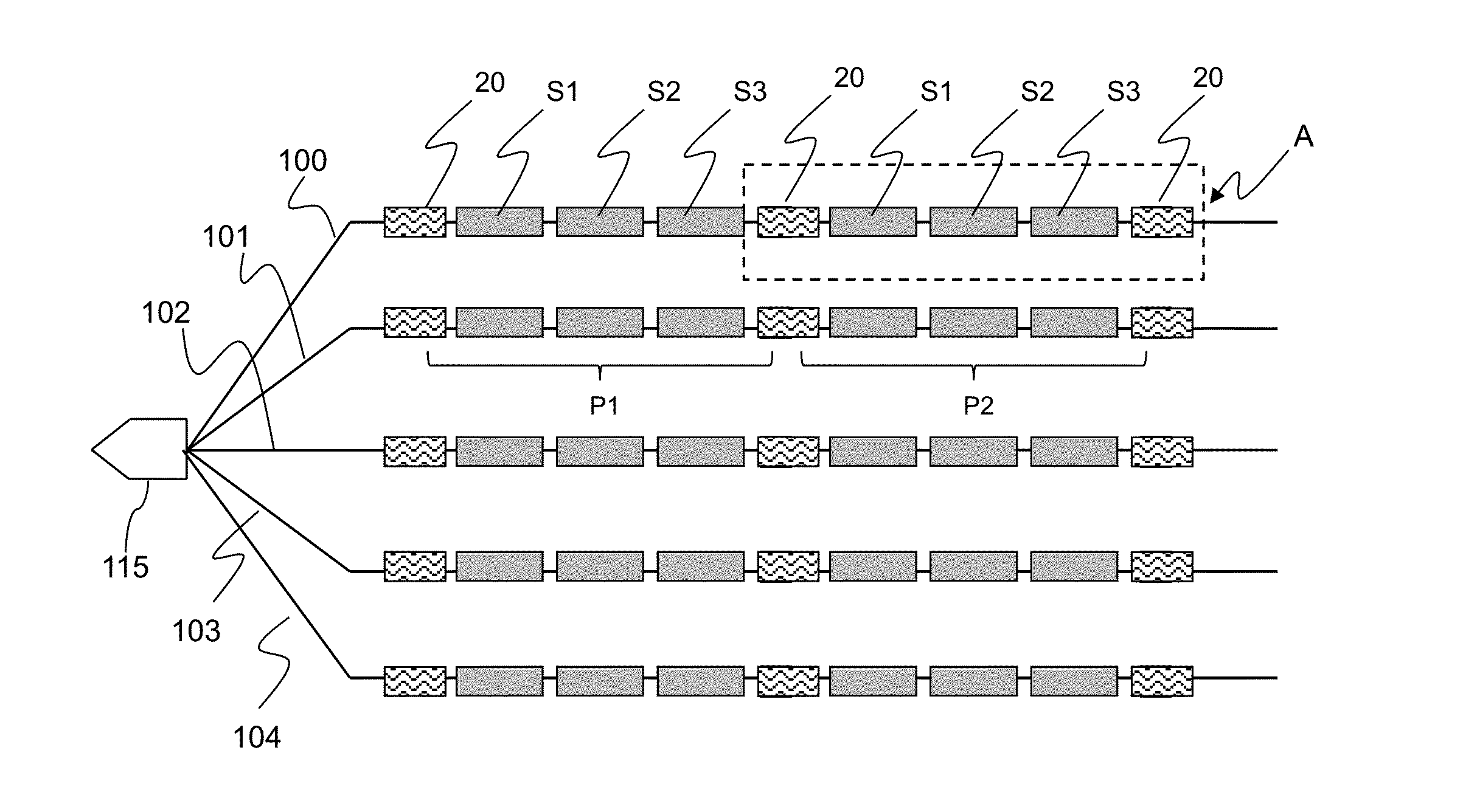
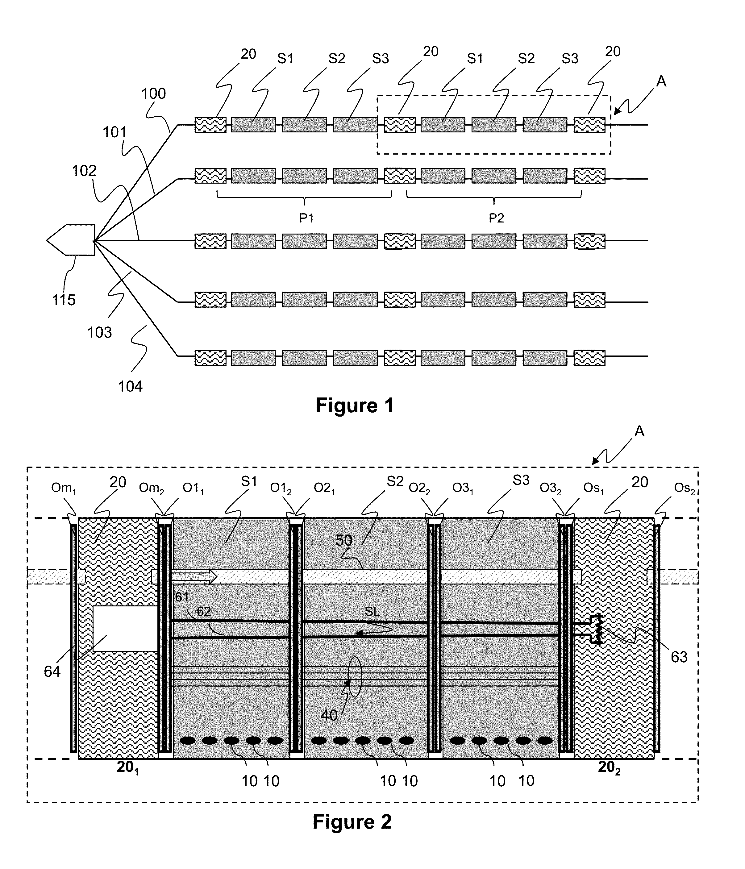
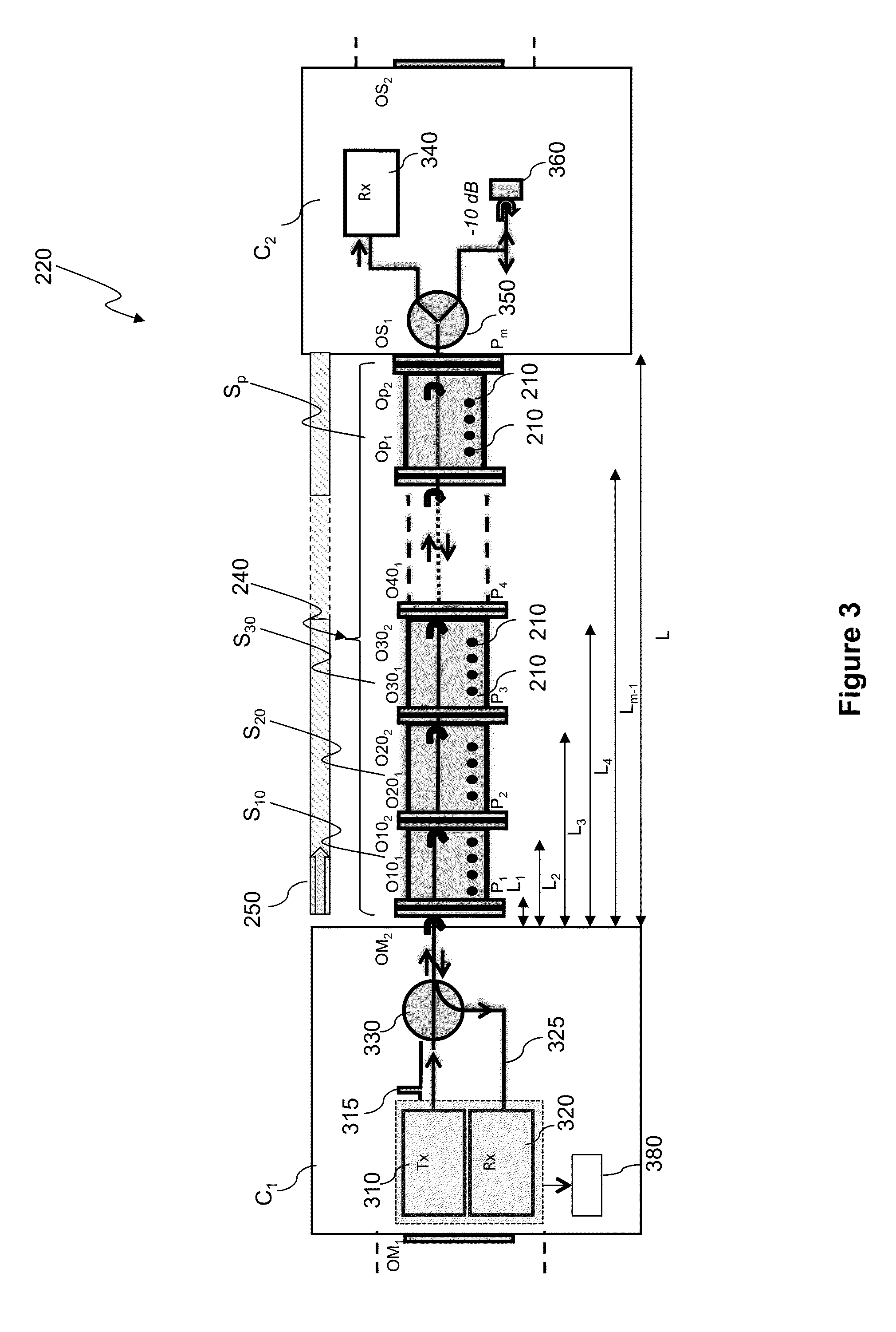
[0108]In all of the figures of the present document, identical elements and steps are designated by the same numerical reference sign. The invention relies on the use of a safety optical loop to carry out the monitoring of an electrical power supply line within a seismic cable.

[0109]The seismic cable according to the invention comprises:[0110]a plurality of seismic sensors arranged along the seismic cable,[0111]a plurality of controllers arranged along the seismic cable,[0112]an electrical transmission line (not shown on FIGS. 3 to 6) extending along the seismic cable for conveying electrical data signals between controllers and nodes,[0113]an optical transmission line extending along the seismic cable for conveying optical data signals from or towards the controllers, and from or towards the seismic vessel.[0114]an electrical power supply line supplying power to the controllers.

[0115]The electrical transmission line typically comprises at least one pair of copper wires. It conveys ...


PUM


Abstract

It is proposed a method for monitoring an electrical power supply line comprised in a seismic cable and extending along the seismic cable. The seismic cable includes: a plurality of seismic sensors arranged along the seismic cable, a plurality of controllers arranged along the seismic cable, and an optical transmission line extending along the seismic cable for carrying data signals from or towards the controllers. The electrical power supply line supplies at least one pair of master and slave controllers. The master controller of a given pair of master and slave controllers performs a step of monitoring a portion of the electrical power supply line between the master and slave controllers, by using an optical loop established on a portion of the optical transmission line between the master and slave controllers, and starting from the master controller and passing through the slave controller.

Description

1. CROSS-REFERENCE TO RELATED APPLICATIONS[0001]This Application claims the benefit of European Patent Application No. EP14305240.5, filed on Feb. 21, 2014, which is incorporated by reference in its entirety.2. FIELD OF THE INVENTION[0002]The field of the invention is that of equipments for the seismic prospection, and more particularly seismic cables designed for hydrocarbon exploration.[0003]More specifically, the invention pertains to a technique for monitoring an electrical power supply line comprised in a seismic cable.[0004]The present invention can be applied notably, but not exclusively, to marine seismic prospection.3. TECHNOLOGICAL BACKGROUND[0005]It is sought more particularly here below in this document to describe problems existing in the field of marine seismic prospection. The invention of course is not limited tot his particular field of application but is of interest for any technique that has to cope with closely related or similar issues and problems.[0006]In mari...

Claims


Application Information

Patent Timeline
Patent Type & Authority Applications(United States)
IPC IPC(8): G01R31/02G01V1/18G01R15/24
CPCG01R31/021G01V1/38G01V1/18G01R15/24G01V1/201G01R31/083G01M11/083G01R31/58
Inventor SELLIN, ISABELLE
Owner SERCEL INC
Learn More