Storage battery structure

a storage battery and battery body technology, applied in the direction of cell components, service/maintenance of secondary cells, cell components, etc., can solve the problems of inconvenient use of materials in modifying materials, inability to claim inventions disclosed by the prior art, and insufficient safety of materials, so as to reduce the self-discharge rate, reduce the effect of impedance and resistance to over-discharg

Inactive Publication Date: 2015-09-03
HUANG HSUEH HUNG
View PDF3 Cites 0 Cited by
  • Summary
  • Abstract
  • Description
  • Claims
  • Application Information

AI Technical Summary

Benefits of technology

[0013]Another objective of the present invention lies in using the structure of the present invention in combination with the microelement structures to achieve effects including effectively reducing impedance, lowering the self-discharge rate, providing resistance to over-discharge, and enabling a fast charging speed, as well as providing a long cycle life, good low temperature capacity performance, good high rate discharge properties, and good high-current output properties.
[0014]A further objective of the present invention lies in substantially reducing the daily amount of sewage produced during the manufacturing process of the present invention, which is less than 20 tons—much lower than the up to 300 tons of sewage discharge produced during the manufacturing process of current products, and better conforms to the demands of environmental protection.

Problems solved by technology

However, in reality, the inventions disclosed by the prior art can not be said to be inventions having characteristics able to complement the target material requiring to be modified and bring the most effective features into full play.
However, if the natural minerals, ceramic, coal, charcoal, and the like, have impurities and foreign substances that dissolve and separate out, then such materials are far from being perfect from a safety aspect.
Because every metal material has its own characteristics, thus, when combined with natural minerals, if no long term experiments have been carried out to accumulate changes therein, then such materials are not suitable for use in modifying materials.
Thus it can be seen that the aforementioned changes in the quality of materials of the prior art still have many shortcomings, and in reality are not good designs.

Method used


Image

  • Storage battery structure
  • Storage battery structure
  • Storage battery structure

Examples


Embodiment Construction

[0019]In order for the aforementioned objectives, features and advantages of the present invention to be clearly and easy to understand, the preferred embodiments disclosed in the present invention, with the accompanying drawings, are described in detail below.

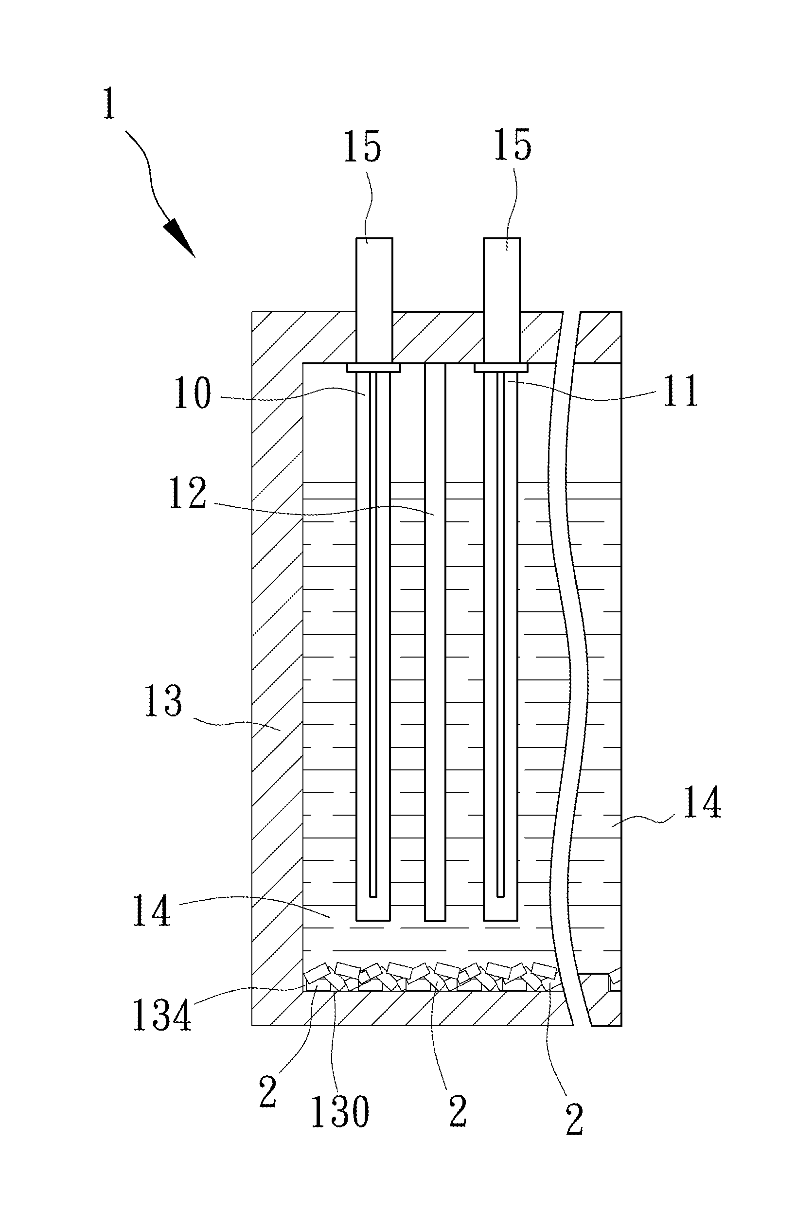
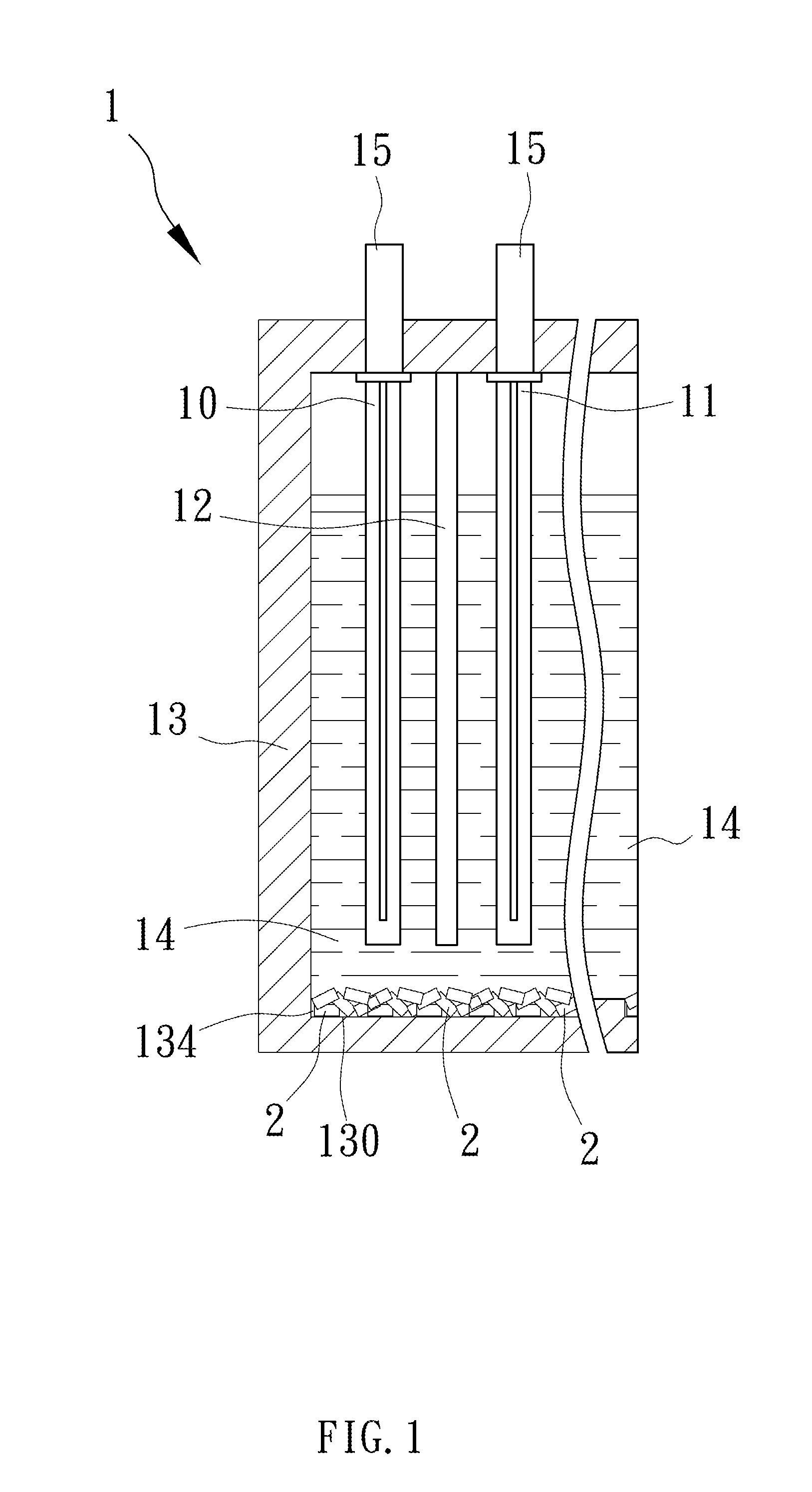
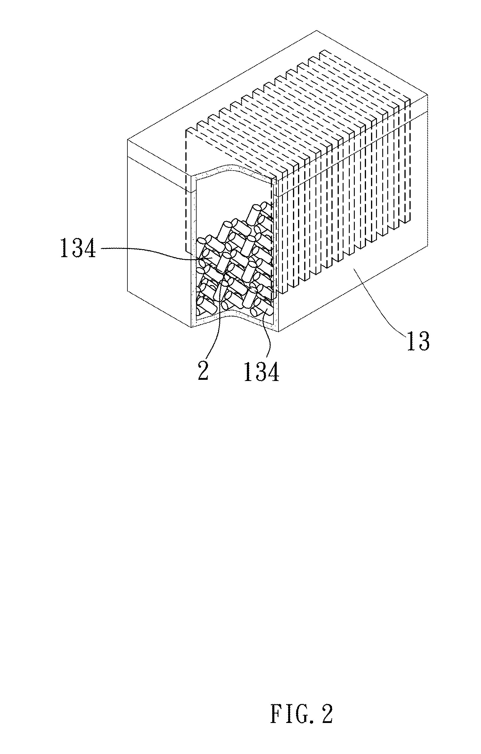
[0020]Current storage batteries, also known as lead-acid storage batteries, are one type of battery with the electrodes primarily made of lead. Another type of storage battery has an electrolyte of sulfuric acid solution. In general, a storage battery comprises positive plates, negative plates, separating plates, a battery compartment, an electrolyte, and wiring portions. The positive plates are lead dioxide (PbO2) plates, and the negative plates are lead (Pb) plates. The battery casing and upper cover are made from ABS (acrylonitrile butadiene styrene) synthetic resin, which has excellent resistance to being struck, as well as being nonflammable. The positive and negative plates are made from a corrosion resistant lead-calciu...


PUM

PropertyMeasurementUnit
distanceaaaaaaaaaa
temperatureaaaaaaaaaa
corrosion rateaaaaaaaaaa

Abstract

A storage battery structure assembled from positive plates, negative plates, plates, a battery compartment, an electrolyte, wiring portions, and a plurality of microelement structures disposed in the bottom portion of the battery compartment. Each of the microelement structures enable the battery structure to produce highfield activated molecular vibration frequencies, thereby changing the molecular structure of the electrolyte to achieve accelerated ionic exchange rates, accelerated charging times, increased conversion rates, reduced accumulating blockage of lead sulfate crystals, reduced corrosion rate of the positive plates, and extended battery life.

Description

BACKGROUND OF THE INVENTION[0001](a) Field of the Invention[0002]The present invention relates to a storage battery structure able to accelerate the charging speed, increase the conversion rate, reduce the accumulated blockage of lead sulfate crystals, reduce the corrosion rate of the positive plate, and extend the service life of the battery, thereby achieving the environmental objective of reducing wastage of natural resources, providing green energy, and reducing carbon emissions.[0003](b) Description of the Prior Art[0004]As is well known, natural minerals such as granite, zeolite and meng moli pumice all provide a positive ion exchange effect or the capacity to use far infrared rays to produce a non-thermal effect. Furthermore, metals such as silver and copper have the capacity to provide a bactericidal effect and the capacity of conductivity. The far infrared rays and positive ions produced by coal and charcoal (such as activated charcoal, hard charcoal, and bamboo charcoal) h...

Claims


Application Information

Patent Timeline
Patent Type & Authority Applications(United States)
IPC IPC(8): H01M10/42
CPCH01M10/4235H01M10/08H01M2300/0011Y02E60/10Y02P70/50
Inventor HUANG, HSUEH-HUNG
Owner HUANG HSUEH HUNG
Why Eureka
Try Eureka