
Method for Detecting Deflection of the Blades of a Wind Turbine

a wind turbine and blade technology, applied in the direction of motors, image data processing, avoiding excessive blade deflection, etc., can solve the problems of catastrophic damage to the whole turbine, and achieve the effect of easily and quickly detecting structural damag

Inactive Publication Date: 2015-09-10
BUNGE STEFFEN
View PDF15 Cites 24 Cited by
  • Summary
  • Abstract
  • Description
  • Claims
  • Application Information

AI Technical Summary

Benefits of technology

The present invention provides a method to quickly and effectively detect deflection of the blades of a wind turbine to assess its structural integrity. The method uses hub / blade mounted cameras to verify the mechanical deflection under a variety of load scenarios. The cameras can be easily mounted on multiple turbines and can quickly be changed over to the next turbine or assessed simultaneously with a low cost of equipment. This method helps to prevent structural damage causing unacceptable deflection and ensures the safe operation of the wind turbine.

Problems solved by technology

Using this method it may be possible to readily detect structural damage of the type causing unacceptable deflection before the damage to the blade can lead to catastrophic damage to the whole turbine.

Method used


Image

  • Method for Detecting Deflection of the Blades of a Wind Turbine
  • Method for Detecting Deflection of the Blades of a Wind Turbine
  • Method for Detecting Deflection of the Blades of a Wind Turbine

Examples


Embodiment Construction

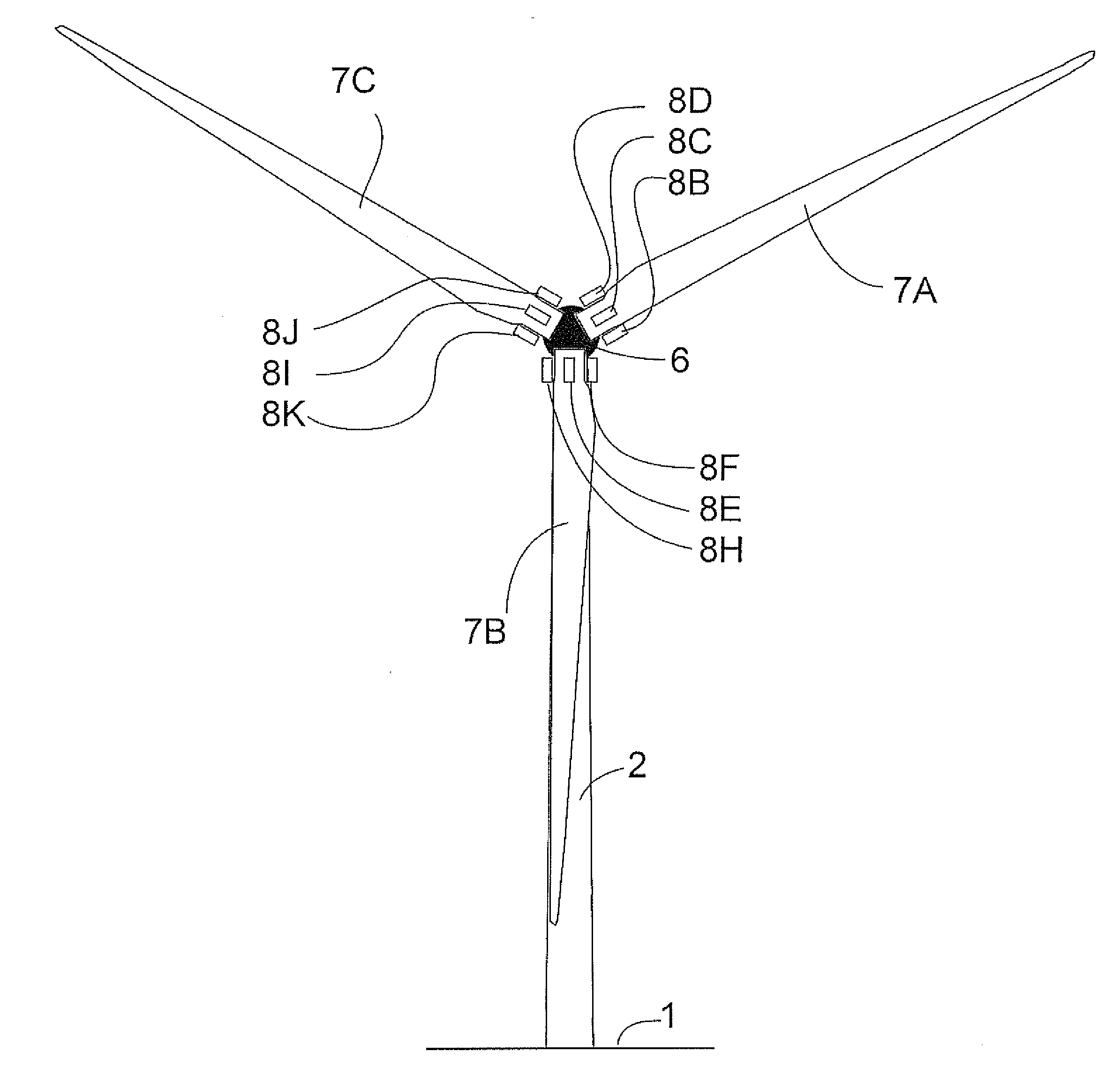
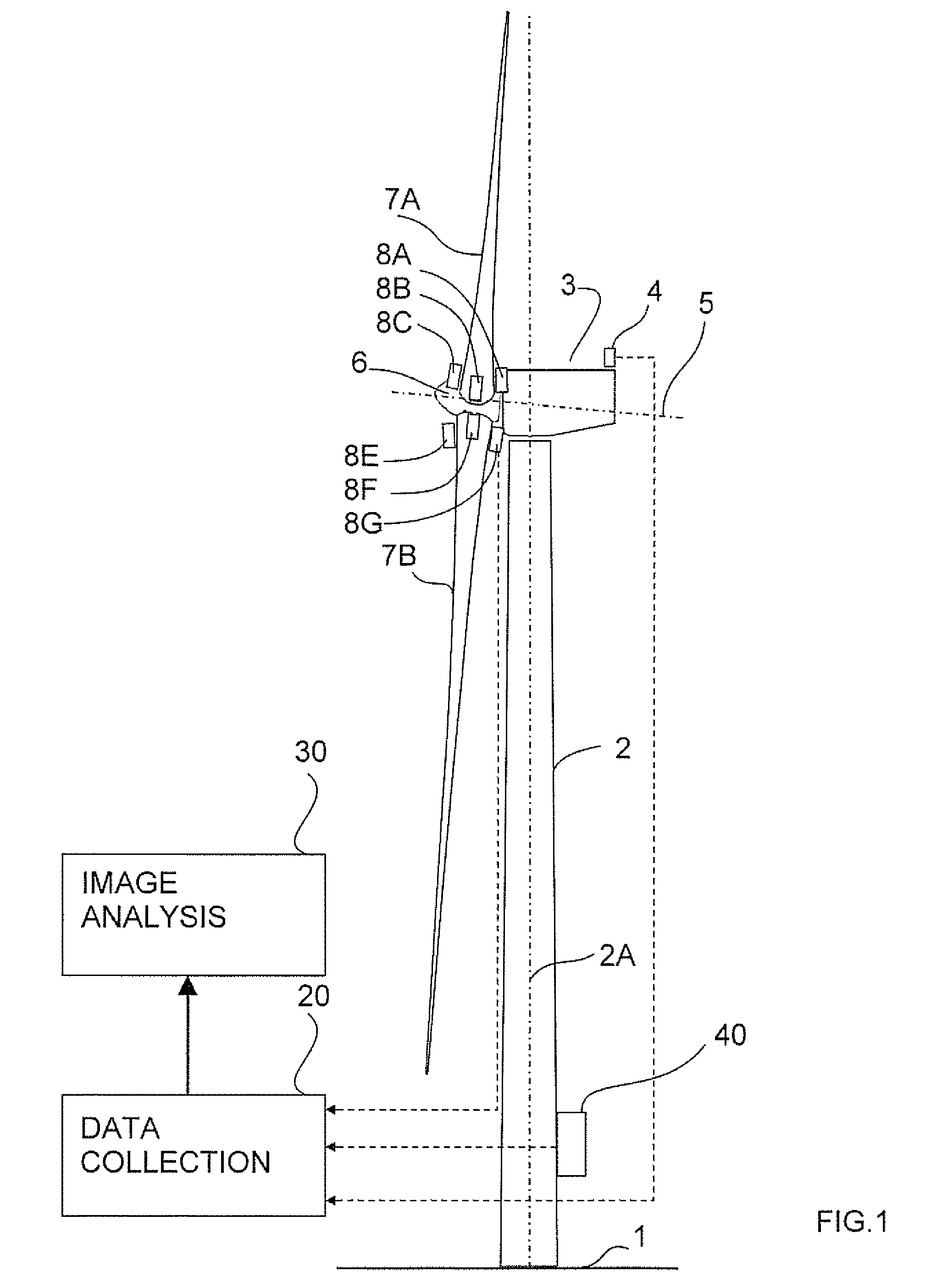
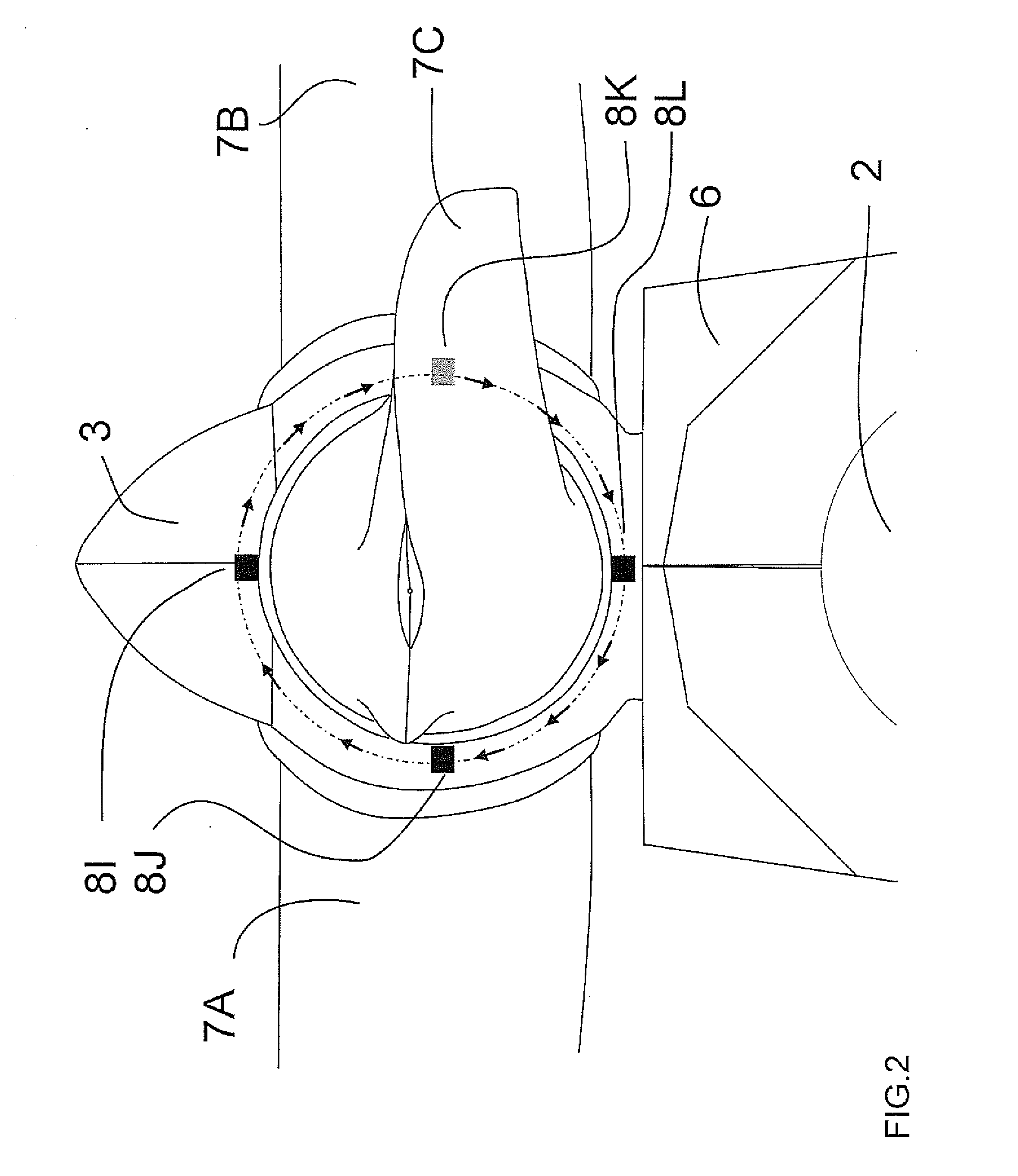
[0049]In FIG. 1 is shown a conventional wind turbine. This includes a nacelle 3 mounted on a tower 2 carried on a base 1. A main shaft (not shown) connects the drive train to the hub and rotor assembly of the hub body 6 carrying the blades 7. There are typically three blades 7A, 7B and 7C arranged at 120 degrees. The blades 7 are mounted at fixed angularly spaced positions around the rotor axis 5.

[0050]The turbine includes a wind detection and control system 4 in the form of an anemometer which analyses the wind speed and direction repeatedly so as to repeatedly adjust the angle of the nacelle 3 around a vertical axis 2A of the tower, that is the angle of the rotor axis relative to the wind direction, and to adjust the angle of attack of the blades 7 around the longitudinal axis of the blade relative to the wind speed.

[0051]The possible positions of the mounting of the video camera 8 on the blades 7A and 7B in relation to the hub 6 are shown in FIG. 1 as follows:

[0052]8A is located ...


PUM


Abstract

An amount of the deflection of the blades of a rotor of a wind turbine of the type including a tower and a nacelle mounted to the top of the tower, the rotor being rotatably connected to the nacelle for rotating about a rotor axis and having a plurality of equally spaced blades includes positioning video cameras on the rotor at a root of a respective one of the blades so as to provide a line of sight of the camera along the respective one of the blades to the tip to obtain a video image of the rotor and tip and carrying out an analysis of the images of the tip to determine a position of the tip and hence the deflection of the tip time synchronized analyzed potentially with external data providing load, capacity, power produced or environmental data.

Description

[0001]This application claims the benefit under 35 USC 119 (e) of Provisional Application 61 / 947828 filed Mar. 4, 2014.[0002]This invention relates to a method for detecting deflection of the blades a rotor of a wind turbine of the type comprising a tower and a nacelle mounted to the top of the tower, the rotor being rotatably connected to the nacelle for rotating about a rotor axis and having a plurality of equally spaced blades around the axis.BACKGROUND OF THE INVENTION[0003]Wind turbines in HAVVT design (horizontal axis) consist of four main parts as a structure, the base, the tower, the nacelle and the rotor with one or more blades.[0004]The blades are mounted at fixed angularly spaced positions around the axis. The turbine includes a wind detection system which analyses the wind speed and direction repeatedly so as to repeatedly adjust the angle of the nacelle around a vertical axis of the tower, that is the angle of the rotor axis relative to the wind direction, and to adjust...

Claims


Application Information

Patent Timeline
Patent Type & Authority Applications(United States)
IPC IPC(8): F03D11/00F03D1/06G06T7/00F03D11/04
CPCF03D11/0091F03D11/04G06T2207/30108G06T7/0004G06T2207/10016F03D1/0675F05B2270/17F05B2270/8041F03D17/00Y02E10/72
Inventor BUNGE, STEFFEN
Owner BUNGE STEFFEN
Learn More