
"Boring Bar with Improved Stiffness"

a boring bar and improved technology, applied in boring bars, manufacturing tools, transportation and packaging, etc., can solve problems such as inability to produce finished workpieces that are not to be used, poor surface finish, and inability to meet the requirements of use, so as to reduce the amplitude of vibration of the bar during use, increase the static stiffness of the bar, and improve the dynamic stiffness

Active Publication Date: 2015-09-17
KENNAMETAL INC
View PDF8 Cites 11 Cited by
  • Summary
  • Abstract
  • Description
  • Claims
  • Application Information

AI Technical Summary

Benefits of technology

The patent describes a special boring bar that can be adjusted to make it easier to use and reduce vibration during use. The boring bar has a tubular body with a cavity and a core layer made of a material with a different modulus of elasticity than a coating layer. The two layers are either bonded together or used as separate layers. The result is a boring bar that is easier to tune and works better during use.

Problems solved by technology

The relative motion between the workpiece and the tool is magnified by this fluctuation of the cutting force and may lead to an unstable condition known as chatter.
As a result of this vibration, a poor quality surface finish and an out-of-tolerance finished workpiece may be produced.
Chatter may be especially problematic when the cutting tool is coupled to an elongated boring bar.
However, this approach interferes with production output leading to low productivity.
However, solid carbide boring bars are more expensive than conventional steel bars.
Furthermore, with solid carbide boring bars, although chatter and vibration are reduced by the inherently high stiffness of the solid carbide bar, vibration may still build to an unacceptable level.
Additionally, solid carbide is fairly brittle and a minor impact upon the boring bar during use or setup may inadvertently damage the bar.
Therefore, tunable boring bars generally are not made from stiffer materials, such as carbide, which cannot be machined through conventional means.
However, even tunable boring bars and AVB bars do not produce satisfactory performance for boring bars with narrow diameter and longer length.
This limitation is problematic since, for certain cutting applications, narrow long length boring bars are particularly desirable.
Also, steel tunable boring bars even when dynamically stable may not have high enough static stiffness to prevent deflection, which may limit the ability of achieving desirable dimensional part quality.
However, as described above, solid carbide is expensive, heavy, and brittle, making it less useful for certain applications.

Method used


Image

  • "Boring Bar with Improved Stiffness"
  • "Boring Bar with Improved Stiffness"
  • "Boring Bar with Improved Stiffness"

Examples


Embodiment Construction

[0029]For purposes of the description hereinafter, spatial orientation terms, if used, shall relate to the referenced embodiment as it is oriented in the accompanying drawing figures or otherwise described in the following detailed description. However, it is to be understood that the embodiments described hereinafter may assume many alternative variations and embodiments. It is also to be understood that the specific devices illustrated in the accompanying drawing figures and described herein are simply exemplary and should not be considered as limiting.

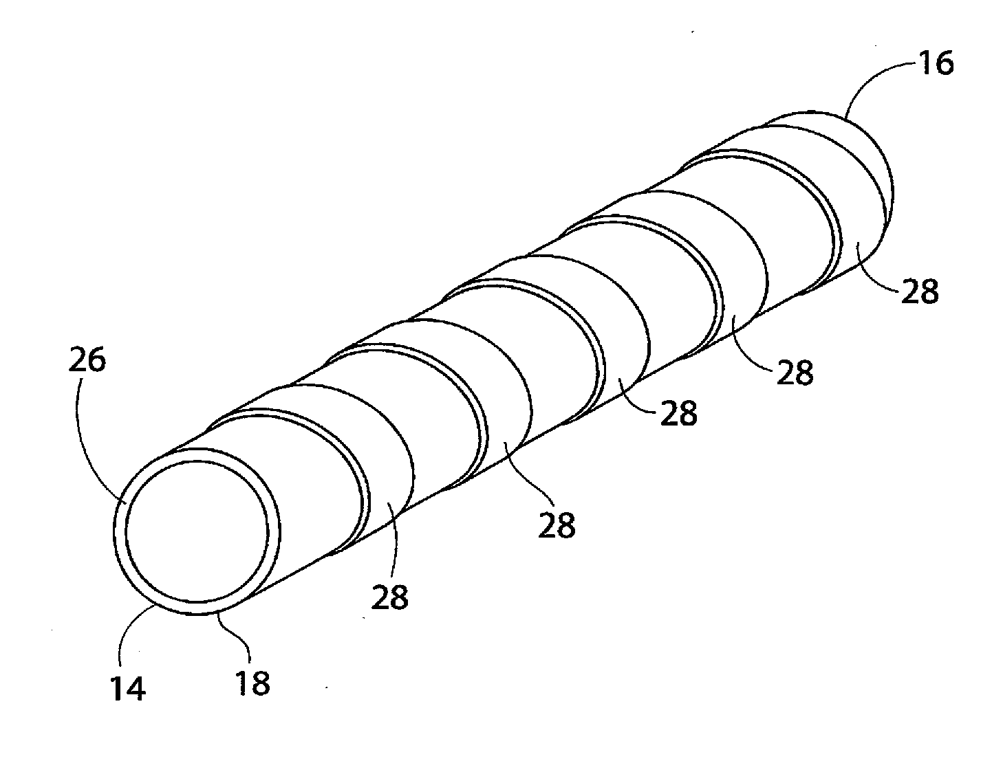
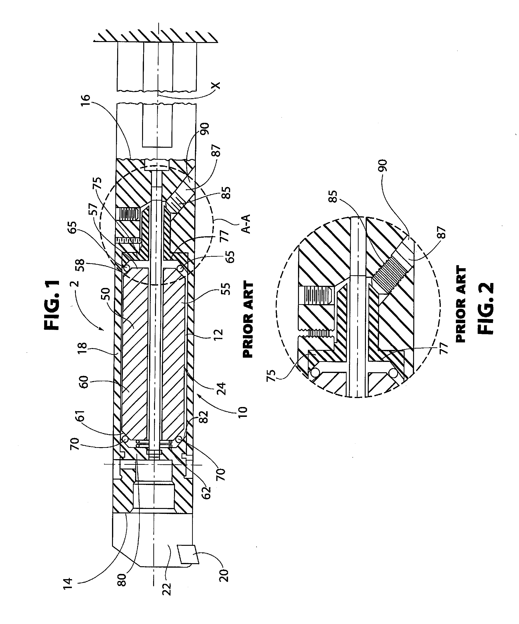
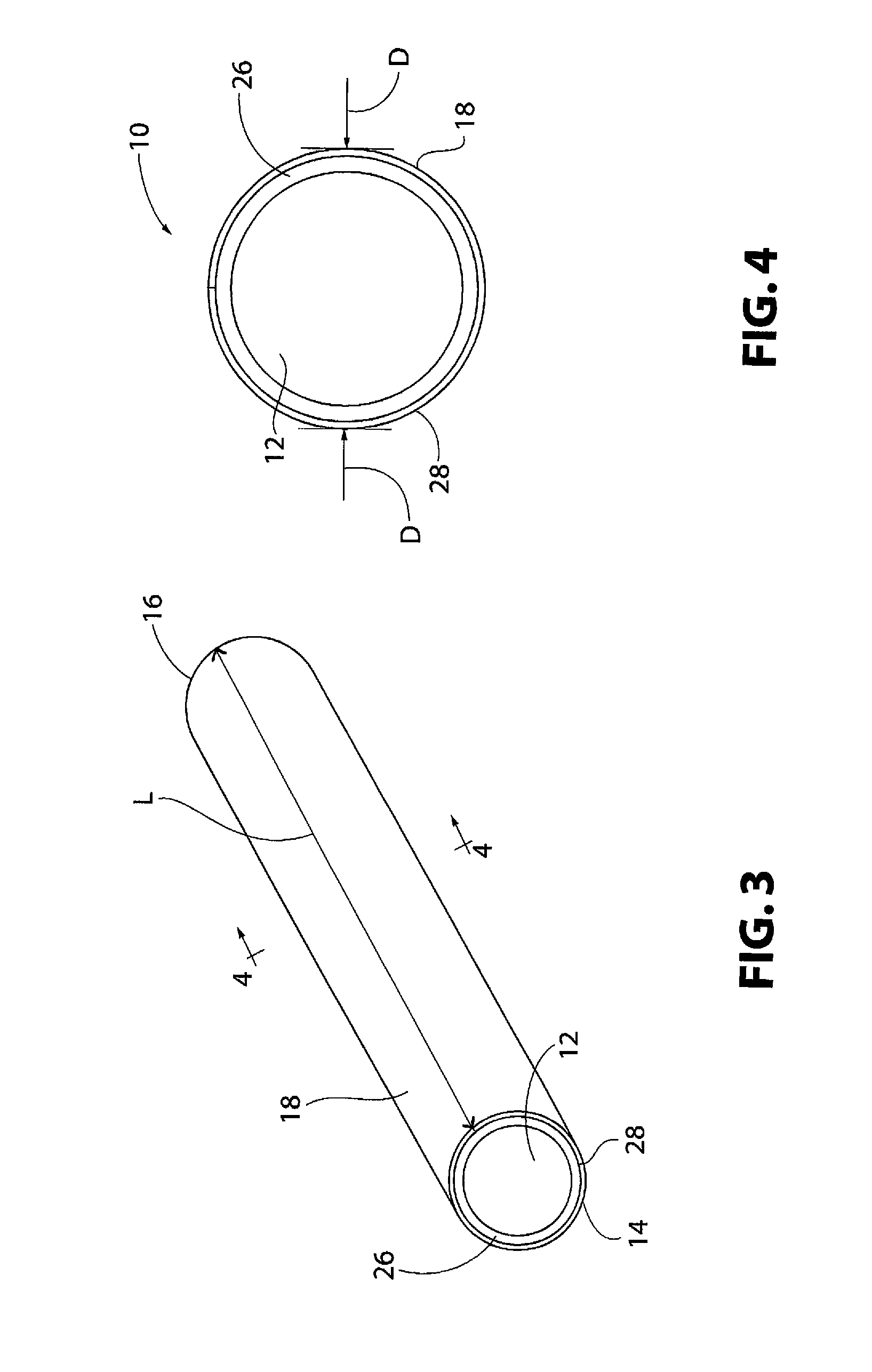
[0030]The present invention is directed to a boring bar 10 used for boring deep holes in work pieces. The boring bar 10 has high dynamic stiffness, which reduces lateral deformation of the bar 10 during use. To facilitate discussion, a toolholder assembly 2, including tunable boring bar 10, having a dynamic anti-vibration mechanism, as is known in the prior art, will now be described. However, the subject invention may also be used ...


PUM

PropertyMeasurementUnit
diameteraaaaaaaaaa
diameteraaaaaaaaaa
natural frequencyaaaaaaaaaa

Abstract

A tunable or tuned boring bar having increased stiffness is provided. Increasing the stiffness of the bar increases the natural frequency, thereby reducing directional deformation of the bar during use. The tunable boring bar includes a distal portion configured to support a tool, a proximal portion configured for attachment to a support structure of a metalworking machine, and a body, which is at least partially tubular, extending between the proximal portion and the distal portion. The tubular portion of the body has an elongated cylindrical cavity. The body of the boring bar includes a core layer formed from a first material and a coating layer formed from a second material. The second material has a higher modulus of elasticity than the first material. In certain configurations, the coating layer is bonded to the core layer by cladding, welding, chemical adhesives, chemical vapor deposition, pulsated plasma diffusion, or combinations thereof.

Description

BACKGROUND OF THE INVENTION[0001]1. Field of the Invention[0002]This invention relates to a boring bar for suppressing vibrations caused in machining processes and, more particularly, to a tunable boring bar, in which at least a portion of the bar body is clad with a material having a high stiffness.[0003]2. Description of Related Art[0004]During a metalworking operation, there is relative motion between a workpiece and a cutting tool being urged against the workpiece. Specifically, the surface finish left on the workpiece by a previous pass of the cutting tool creates variation in chip thickness that, in turn, creates fluctuation of the cutting force magnitude. The relative motion between the workpiece and the tool is magnified by this fluctuation of the cutting force and may lead to an unstable condition known as chatter. Chatter is an example of self-excited vibration. As a result of this vibration, a poor quality surface finish and an out-of-tolerance finished workpiece may be p...

Claims


Application Information

Patent Timeline
Patent Type & Authority Applications(United States)
IPC IPC(8): B23B29/02B23P15/28
CPCB23B29/022B23P15/28B23B2250/16B23B2222/80B23B2226/275B23B47/00B23B51/08B23B27/002B23B27/007C23C24/103Y10T408/76Y10T408/78
Inventor FROTA DE SOUZA FILHO, RUY
Owner KENNAMETAL INC
Learn More