Transmission apparatus

a technology of transmission apparatus and transmission shaft, which is applied in the direction of mechanical control devices, gearing, instruments, etc., can solve the problems of unnecessary rotation loss and heat generation, and achieve the effect of smooth operation

Active Publication Date: 2015-09-17
HONDA MOTOR CO LTD
View PDF1 Cites 6 Cited by
  • Summary
  • Abstract
  • Description
  • Claims
  • Application Information

AI Technical Summary

Benefits of technology

[0013]According to the embodiment, the coupling element is the synchronizer (synchromesh mechanism), and the movable member is the shift fork that engages with the synchronizer sleeve to cause a displacement in an axial direction. Further, the opening formed in the circumferential side surface of the attachment member and that allows the insertion of the movable member includes two openings for inserting the shift fork. Still further, an additional opening is provided in the circumferential side surface of the attachment member. Accordingly, when assembling the planetary gear mechanism and the synchronizer arranged therein to one end of the first gear shaft, in a state where the ring gear, the planetary gears, and elements relating to the synchronizer are combined, the human operator's finger or fingers can be inserted from the additional opening from outside the attachment member. As a result, it is possible to retain the member (such as the planetary gears and the elements related to the synchronizer) inside the attachment member with the inserted finger or fingers, the assembly work can be smoothly carried out.

Problems solved by technology

In particular, in a high vehicle speed region, despite the fact that the planetary gear mechanism 40 is not involved in changing speeds, a large differential speed is generated due to rotation caused by dragging, which results in unnecessary rotation loss as well as generation of heat due to rotational friction.

Method used


Image

  • Transmission apparatus
  • Transmission apparatus
  • Transmission apparatus

Examples


Embodiment Construction

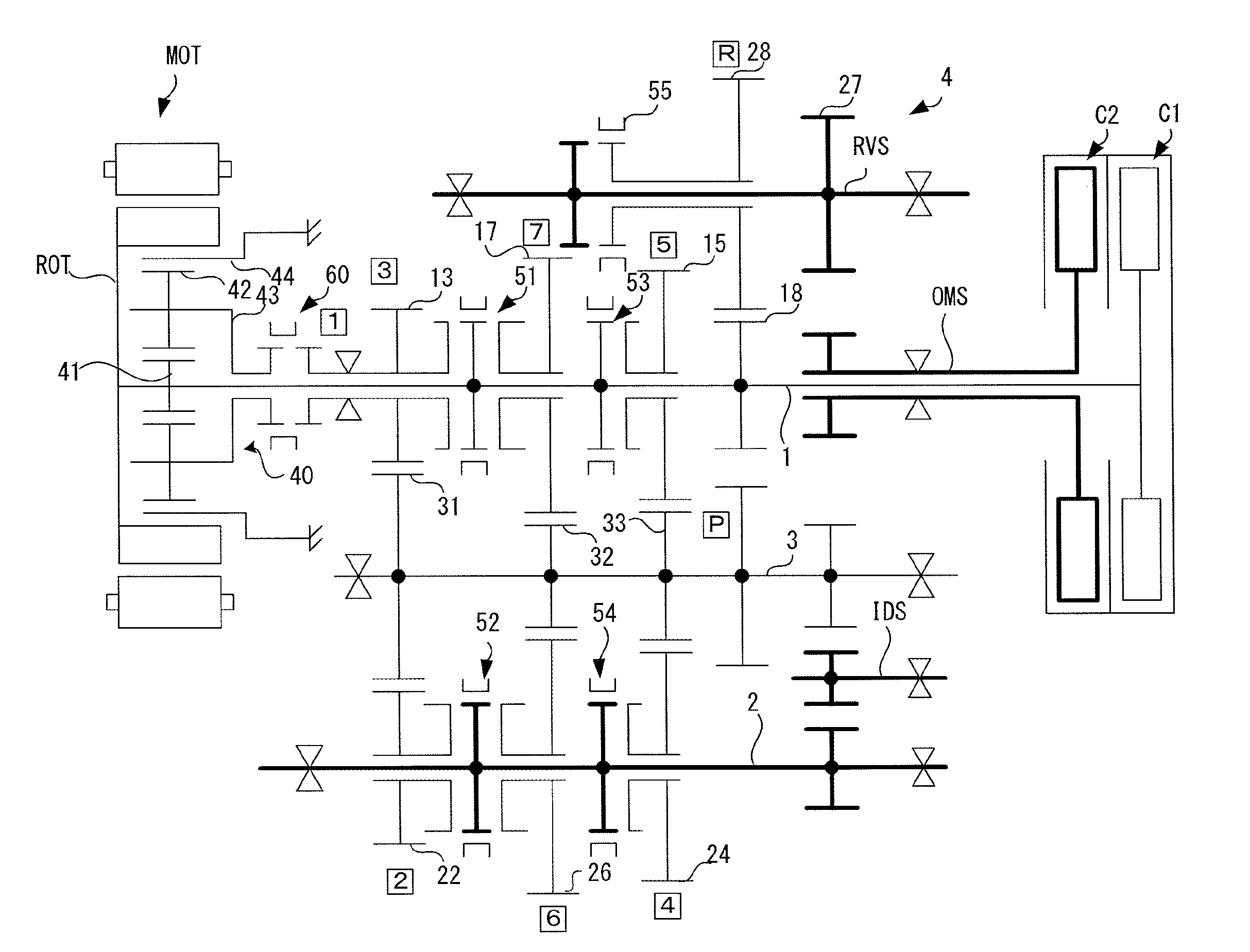
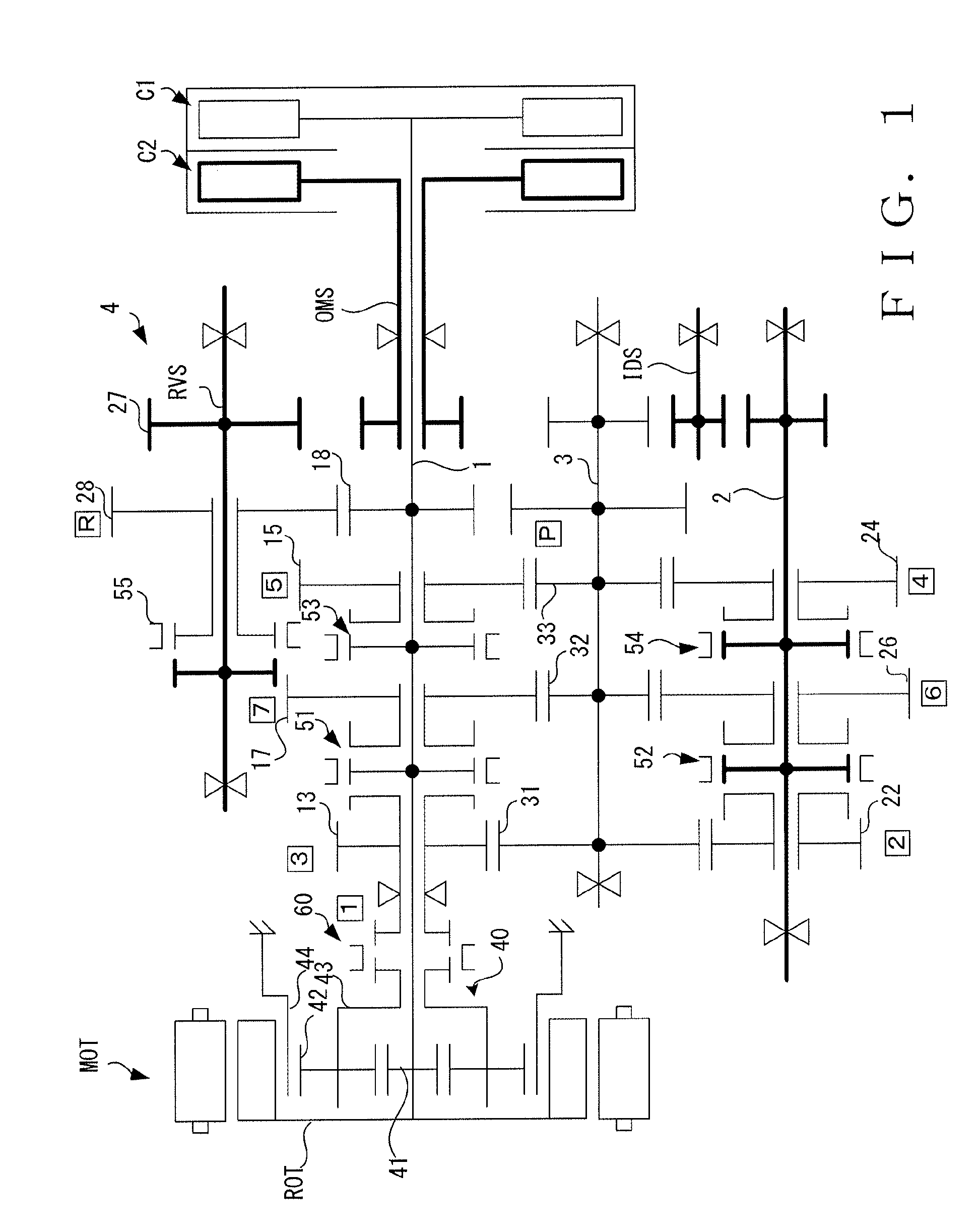
[0021]FIG. 1 is a skeleton diagram of a transmission apparatus 4 according to one embodiment of the invention. The transmission apparatus 4 is a parallel shaft transmission with seven forward gears and one reverse gear, and is also a dry dual clutch transmission (DCT).

[0022]The transmission apparatus 4 includes a first input shaft (namely, first gear shaft) 1 that is connected to the internal combustion engine (not shown) in a disconnectable manner via a first clutch (namely, first connecting / disconnecting means) C1 for odd-numbered speed stages, a second input shaft (namely, second gear shaft) 2 that is connected to the internal combustion engine in a disconnectable manner via the second clutch C2 for even-numbered speed stages, and a countershaft (namely, drive output shaft) 3 that connects to the respective input shafts (gear shafts) 1, 2 via a speed-change mechanism provided on the respective input shafts (gear shafts) 1, 2 and that generates a rotation force corresponding to th...


PUM


Abstract

In a dual clutch transmission, on one end side of a first input shaft connectable to an internal combustion engine via a first clutch, a planetary gear mechanism for a predetermined speed stage is provided, and a sun gear thereof is provided to rotate integrally with the first input shaft and an electric motor. A ring gear is fixed to a case, and a synchromesh mechanism is provided connectably and disconnectably with respect to the planetary gear carrier for selecting the predetermined speed stage. When the synchromesh mechanism is connected to the planetary gear carrier, rotation of the carrier is transmitted to the countershaft. The ring gear is attached to an annular attachment member to be fixed to the case. In a circumferential side surface of the attachment member, openings for inserting a shift fork and an opening for inserting a finger for the convenience of assembly work are provided.

Description

TECHNICAL FIELD[0001]The invention relates to a transmission apparatus (power transmission apparatus) for a hybrid vehicle that includes an internal combustion engine and an electric motor as a drive source, and more particularly to an improvement of a power transmission structure that employs a planetary gear mechanism provided in a dual clutch transmission (DCT) that includes, two gear shafts for odd-numbered speed stages and even-numbered speed stages, and a speed-change gear mechanism relating thereto.BACKGROUND ART[0002]International Patent Publication No. WO2010 / 046307 and International Patent Publication No. WO2010 / 110343 disclose conventional technique for a dual clutch transmission (DCT) that includes two gear shafts, for odd-numbered speed stages and even-numbered speed stages, and a speed-change gear mechanism relating thereto, in a hybrid vehicle that includes an internal combustion engine and an electric motor as a drive source. According to these publications, a first ...

Claims


Application Information

Patent Timeline
Patent Type & Authority Applications(United States)
IPC IPC(8): F16H37/04F16H63/32F16D23/02
CPCF16H37/046F16D23/02F16H63/32Y10S903/917F16H2200/2005F16H2702/02F16H2063/025B60K6/365F16H3/001F16H3/44F16H57/02F16H57/08F16H2200/0056F16H3/006F16H61/688
Inventor MINAMINAKAMICHI, TAKASHITOJO, KEIJIFUJIMOTO, SHINJIAKIYAMA, KATSUNORI
Owner HONDA MOTOR CO LTD
Why Eureka
Try Eureka