Combined Cycle Plant With Thermal Energy Storage

Inactive Publication Date: 2015-09-24
VAMVAS VASSILIOS
View PDF9 Cites 19 Cited by
  • Summary
  • Abstract
  • Description
  • Claims
  • Application Information

AI Technical Summary

Benefits of technology

[0019]The latent thermal energy storage and retrieval system is also operatively connected with the heat recovery steam generator to capitalize on the gas exhaust fluid. The exhaust fluid thermally charges the phase change material. The thermal discharge of the energy storage system occurs when the gas turbine is not in operation. One or more bottoming cycle steam turbines can re

Problems solved by technology

Grid operators face challenges to optimally integrate renewable electrical power with traditional dispatchable electrical power, due to the uncertain and intermittent output of the renewable energy plants.
However, this plant is considerably less efficient than a combined cycle plant.
Combined cycle plants though the bottoming steam turbines require a substantial amount of time for a “cold” or even a “hot” startup.
Steam turbine proper preheating for fast startups requires the consumption of a considerable amount of fossil fuels, which lower the plant's efficiency, due to fuel costs and increase environmental pollution.
Also, this novel thermal energy storage system effectively tackles the high thermal resistance of PCMs, during thermal discharge,

Method used


Image

  • Combined Cycle Plant With Thermal Energy Storage
  • Combined Cycle Plant With Thermal Energy Storage
  • Combined Cycle Plant With Thermal Energy Storage

Examples


Embodiment Construction

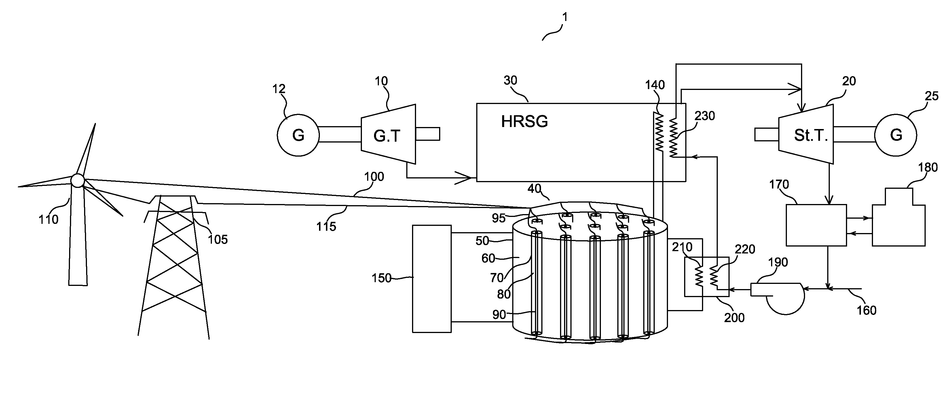
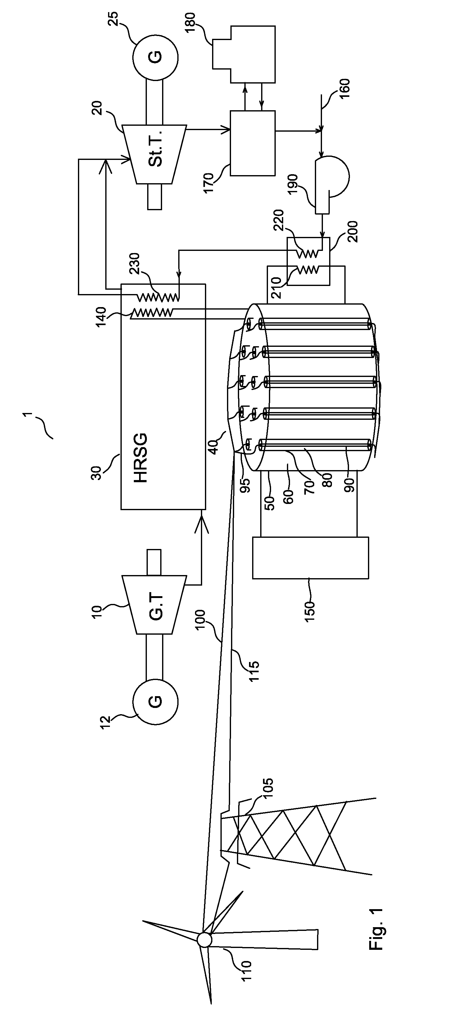
[0022]FIG. 1 shows a combined cycle gas turbine plant 1, which includes at least one gas turbine for topping cycle 10 coupled with generator 12, at least one steam turbine for bottoming cycle 20 coupled with generator 25, and at least one heat-recovery steam generator (HRSG) 30. The combined cycle gas turbine plant 1 utilizes the at least one HRSG 30 to generate a first steam by heat exchange with expanded fluid formed by expanding energetic fluid through the at least one gas turbine 10. The generated steam is expanded through the at least one steam turbine 20. The HRSG 30 is disposed to utilize waste heat in the form of heated exhaust air from the at least one gas turbine 10 in order to vaporize supplied water or condensate and produce a first steam. This steam enters the at least one steam turbine 20.

[0023]The combined cycle gas turbine plant 1 also includes at least one thermal energy storage and retrieval system 40, comprising at least one container 50, which is filled with a he...


PUM


Abstract

A combined cycle power plant for frequent stops and startups comprises at least one gas turbine, a heat recovery steam generator, at least one steam turbine and a thermal energy storage and retrieval system utilizing latent heat of fusion. Phase change materials receive thermal charge from two sources: (a) renewable energy generation plants, when their production exceeds demand and (b) gas turbine exhaust heat. The thermal energy storage and retrieval system, discharges efficiently thermal energy for steam production, which keeps the at least one steam turbine preheated and ready for fast startups, thus increasing the plant's flexibility and efficiency.
A novel two stage latent thermal energy storage system provides at least supercritical steam.

Description

CROSS-REFERENCE TO RELATED APPLICATIONS[0001]This application claims the benefit of U.S. provisional patent application Ser. No. 61 / 954,619, filed 2014 Mar. 18 by the present inventor. Also, this application claims the benefit of U.S. patent application Ser. No. 20140327338 submitted by the same inventor and incorporated herein by reference in its entirety.BACKGROUND[0002]1. Prior Art[0003]The following is a tabulation of some prior art that presently appears relevant:Patents[0004]Pat. No.Kind CodeIssue DatePatentee8,938,966B22015-01-27Jockenhoevel8,739,512B22014-06-03Mills7,971,437B22011-07-05Flynn7,089,727B22006-08-15Schutz[0005]The growing number of renewable electricity production plants, such as wind and solar plants has altered the electricity source mix provided to the electricity grid. Grid operators face challenges to optimally integrate renewable electrical power with traditional dispatchable electrical power, due to the uncertain and intermittent output of the renewable e...

Claims


Application Information

Patent Timeline
IPC IPC(8): F01K3/18F28D20/02F01K13/02F01K7/16F01K23/18F01K23/10
CPCF01K3/186F01K23/18F28D20/026F01K13/02F01K7/16F01K23/10F01K3/00F28D20/02Y02E20/16Y02E60/14Y02E70/30Y02P80/15
Inventor VAMVAS, VASSILIOS
Owner VAMVAS VASSILIOS
Why Eureka
Try Eureka