Exhaust system

a technology of exhaust pipe and exhaust pipe, which is applied in the direction of engine components, mechanical equipment, machines/engines, etc., can solve the problems of electrically disconnected pipes and exhaust pipes, and achieve the effect of reducing the amount of energy needed for this and reducing the risk of undetectable condensation and/or deposit formation

Active Publication Date: 2015-09-24
PUREM GMBH
View PDF6 Cites 26 Cited by
  • Summary
  • Abstract
  • Description
  • Claims
  • Application Information

AI Technical Summary

Benefits of technology

[0006]An object of the present invention is to provide an improved embodiment for an exhaust system of the above-described type or for a corresponding operating method, which embodiment is characterized especially in that the risk of an undesired condensation and / or deposit formation is reduced, and, in addition, the amount of energy needed for this is reduced.

Problems solved by technology

Further, an electric insulator is arranged between the conductor and the outer side of the pipe wall, as a result of which the pipe wall and the exhaust pipe are electrically uncoupled from the electric currents for operating the heating device.
Furthermore, the cover may at the same time bring about an encapsulation for the heating device.

Method used


Image

  • Exhaust system
  • Exhaust system
  • Exhaust system

Examples


Embodiment Construction

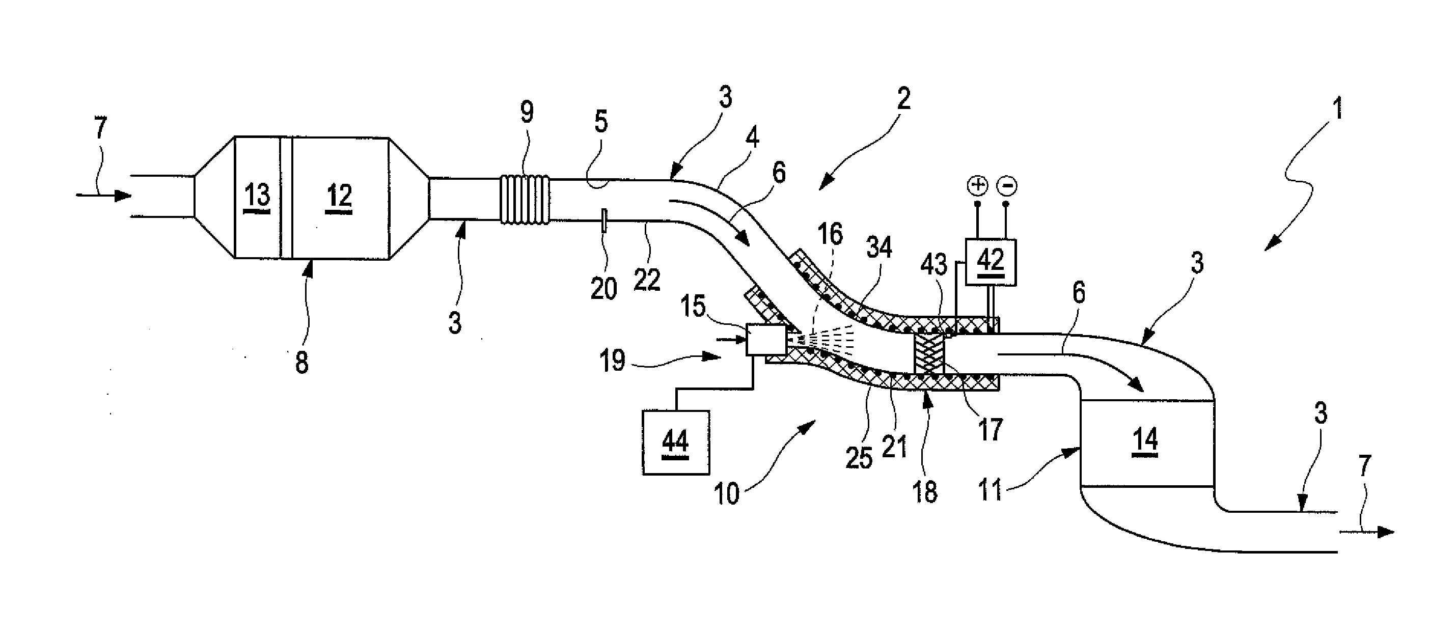
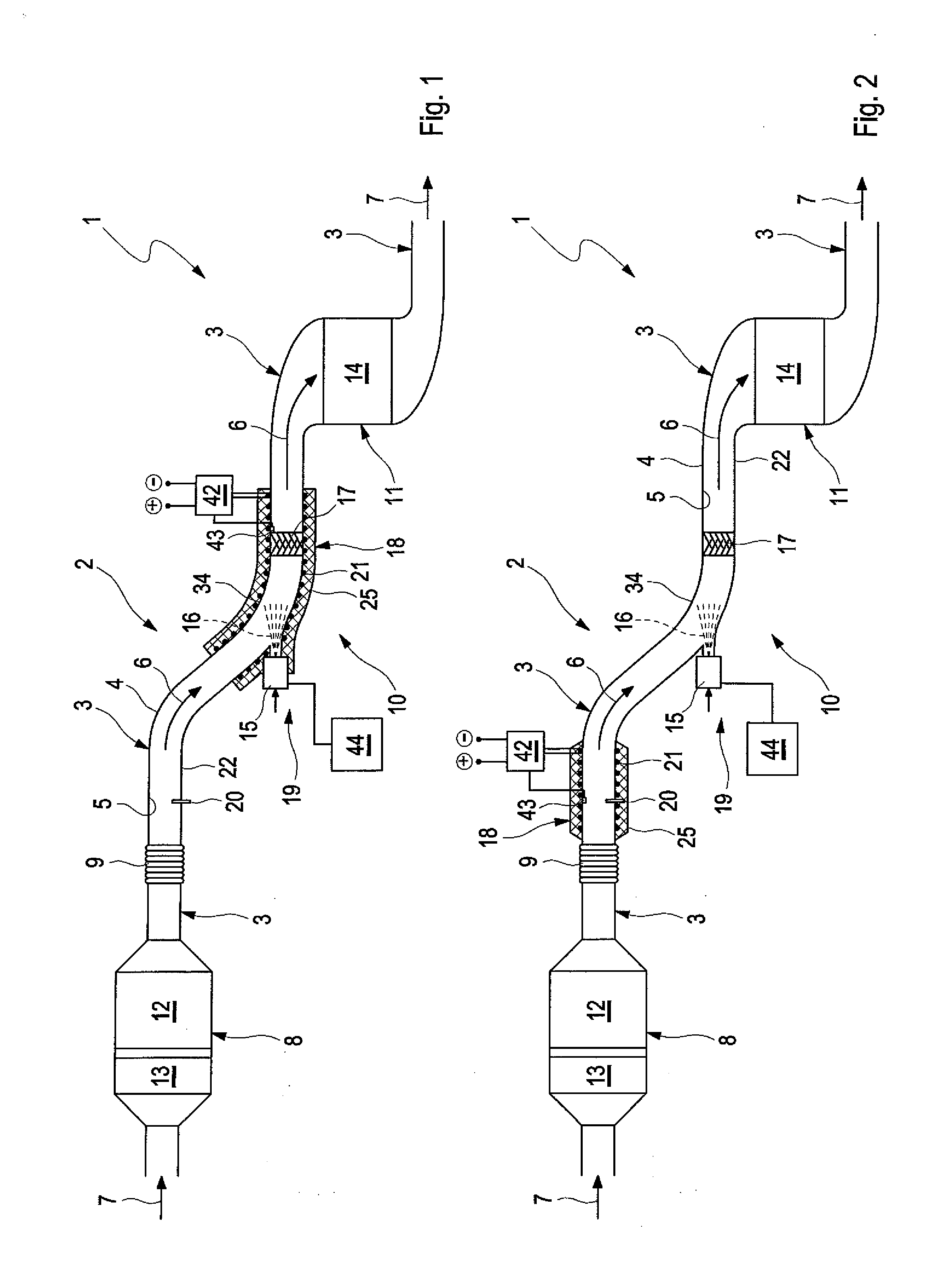
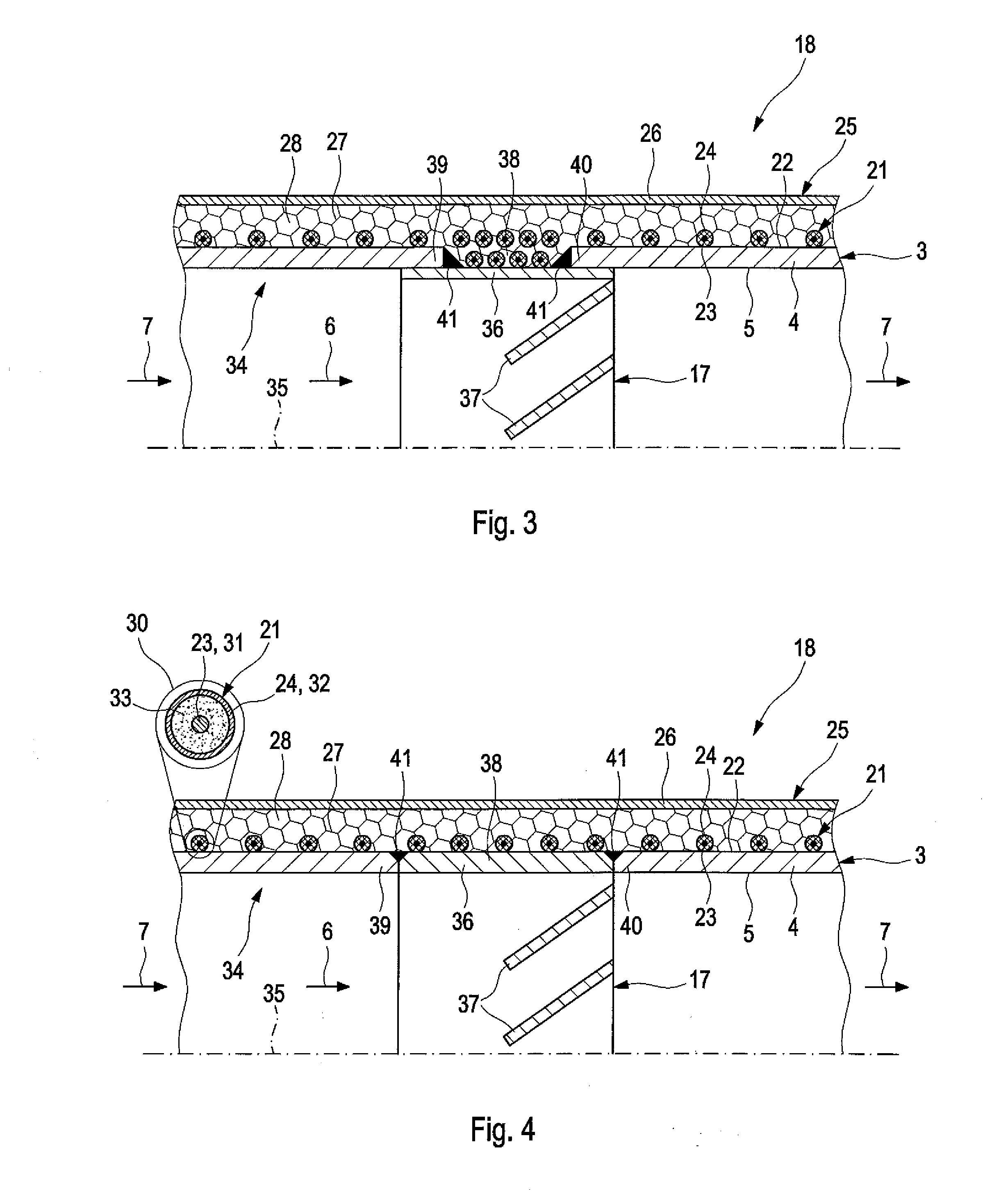
[0033]Referring to the drawings, corresponding to FIGS. 1 and 2, an exhaust system 1 for an internal combustion engine, not shown here, comprises an exhaust line 2, which leads from an engine block of the internal combustion engine to a tail pipe of the exhaust system 1.

[0034]The exhaust line 2 contains for this at least one exhaust pipe 3, which has a pipe wall 4. The pipe wall 4 defines on its inner side 5 an exhaust gas path 6 indicated by arrows in FIGS. 1 and 2 for guiding an exhaust gas flow 7, which is likewise indicated by arrows. Within the exhaust line 2, the exhaust pipes 3 connect individual components of the exhaust system 1, which are arranged in the exhaust line 2, with one another. Purely as an example, a particle filter 8, an uncoupling element 9 and an SCR catalytic converter 11 of an SCR system 10 are provided in FIGS. 1 and 2. The particle filter 8 contains a particle filter element 12 and, upstream of the latter, an oxidation catalytic converter element 13. The ...


PUM


Abstract

An exhaust system (1) for an internal combustion engine has an exhaust line (2), which has at least one exhaust pipe (3) having a pipe wall (4) with an inner side (5) defining an exhaust gas path (6) guiding an exhaust gas flow (7) and an electric heating device (18) for heating at least one length section of the exhaust pipe (3). An efficient design is obtained if a heating coil (21) is wound several times around the exhaust pipe (3) on an outer side (22) of the pipe wall (4) in the respective length section and has an electric conductor (23) made of a resistance heating material. An electric insulator (24) is arranged between the conductor (23) and the outer side (22) of the pipe wall (4). A heat-insulating cover (25) envelops the exhaust pipe (3) at least in the area of the respective heating coil (21).

Description

CROSS REFERENCE TO RELATED APPLICATIONS[0001]This application claims the benefit of priority under 35 U.S.C. §119 of German Patent Application DE 10 2014 205 156.8 filed Mar. 19, 2014, the entire contents of which are incorporated herein by reference.FIELD OF THE INVENTION[0002]The present invention pertains to an exhaust system for an internal combustion engine, which may be arranged especially in a motor vehicle. The present invention pertains, in addition, to a method for operating such an exhaust system.BACKGROUND OF THE INVENTION[0003]An exhaust system comprises, in the usual manner, an exhaust line, which has at least one exhaust pipe, whose pipe wall defines with an inner side an exhaust gas path for guiding an exhaust gas flow. The exhaust line begins at the engine block of the internal combustion engine, as a rule, with an exhaust manifold or exhaust collector and ends towards the surrounding area with at least one tail pipe. A plurality of exhaust gas treatment devices, fo...

Claims


Application Information

Patent Timeline
Patent Type & Authority Applications(United States)
IPC IPC(8): F01N13/08F01N3/20F01N3/025F01N13/14
CPCF01N13/08F01N13/14F01N3/2066F01N2610/03F01N2610/1453F01N2610/02F01N3/0253F01N13/04F01N2240/16
Inventor TOBBEN, HEIKEWIRTH, GEORG
Owner PUREM GMBH
Why Eureka
Try Eureka