Defect Inspection Method and Defect Inspection Device

a defect inspection and inspection method technology, applied in the direction of optically investigating flaws/contamination, optical radiation measurement, instruments, etc., can solve the problems of difficult detection of scattered light from defects, difficulty in illuminating light to the position of bridge defects, and difficulty in detecting scattered light from defects. , to achieve the effect of suppressing diffracted/scattered light, high efficiency and high efficiency

Active Publication Date: 2015-10-01
HITACHI HIGH-TECH CORP
View PDF3 Cites 12 Cited by
  • Summary
  • Abstract
  • Description
  • Claims
  • Application Information

AI Technical Summary

Benefits of technology

[0007]Since the bridge defect exists in a place sandwiched between lines of an L & S pattern having a high aspect ratio and a narrow pitch (short interval), there are cases where having the illuminating light reach the position of the bridge defect is difficult, for example. Further, since the bridge defect has anisotropy in the shape, having the defect cause the scattered light with high efficiency sometimes becomes difficult depending on the correlation between the polarization direction of the illuminating light reaching the defect position and the directional property of the defect. Furthermore, there are also cases where the detection of the scattered light from the defect is difficult due to reflection or absorption of the scattered light from the defect by the L & S pattern around the defect. Moreover, diffracted/scattered light of the illuminating light that is caused by the L & S pattern, roughness of the pattern, disturbance in the periodicity of the pattern, etc. can act as noise and can disable the detection of the scattered light from the defect.
[0008]In consideration of the situation described above, the present invention prov

Problems solved by technology

Since the bridge defect exists in a place sandwiched between lines of an L & S pattern having a high aspect ratio and a narrow pitch (short interval), there are cases where having the illuminating light reach the position of the bridge defect is difficult, for example.
Further, since the bridge defect has anisotropy in the shape, having the defect cause the scattered light with high efficiency somet

Method used


Image

  • Defect Inspection Method and Defect Inspection Device
  • Defect Inspection Method and Defect Inspection Device
  • Defect Inspection Method and Defect Inspection Device

Examples


Embodiment Construction

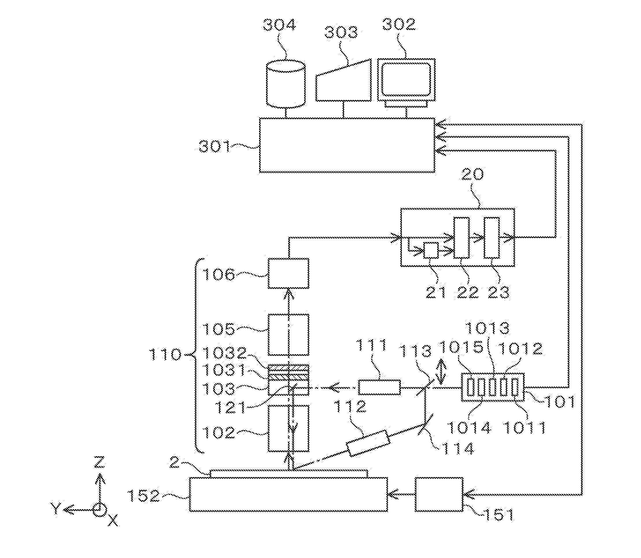
[0037]The present invention relates to a defect inspection method and a defect inspection device for inspecting the status of occurrence of defects in a manufacturing process for manufacturing a product by forming a pattern on a substrate (semiconductor manufacturing process, liquid crystal display element manufacturing process, printed circuit board manufacturing process, etc.) to be used in a process for detecting the defects, analyzing the occurrence of defects and taking countermeasures against the occurrence of defects.

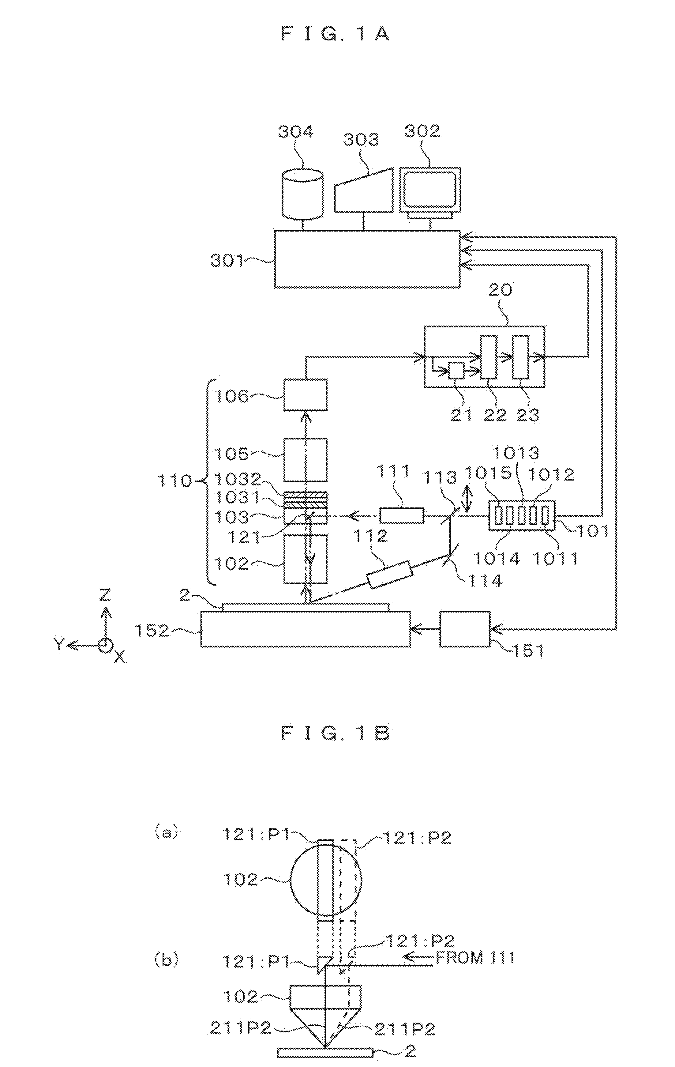
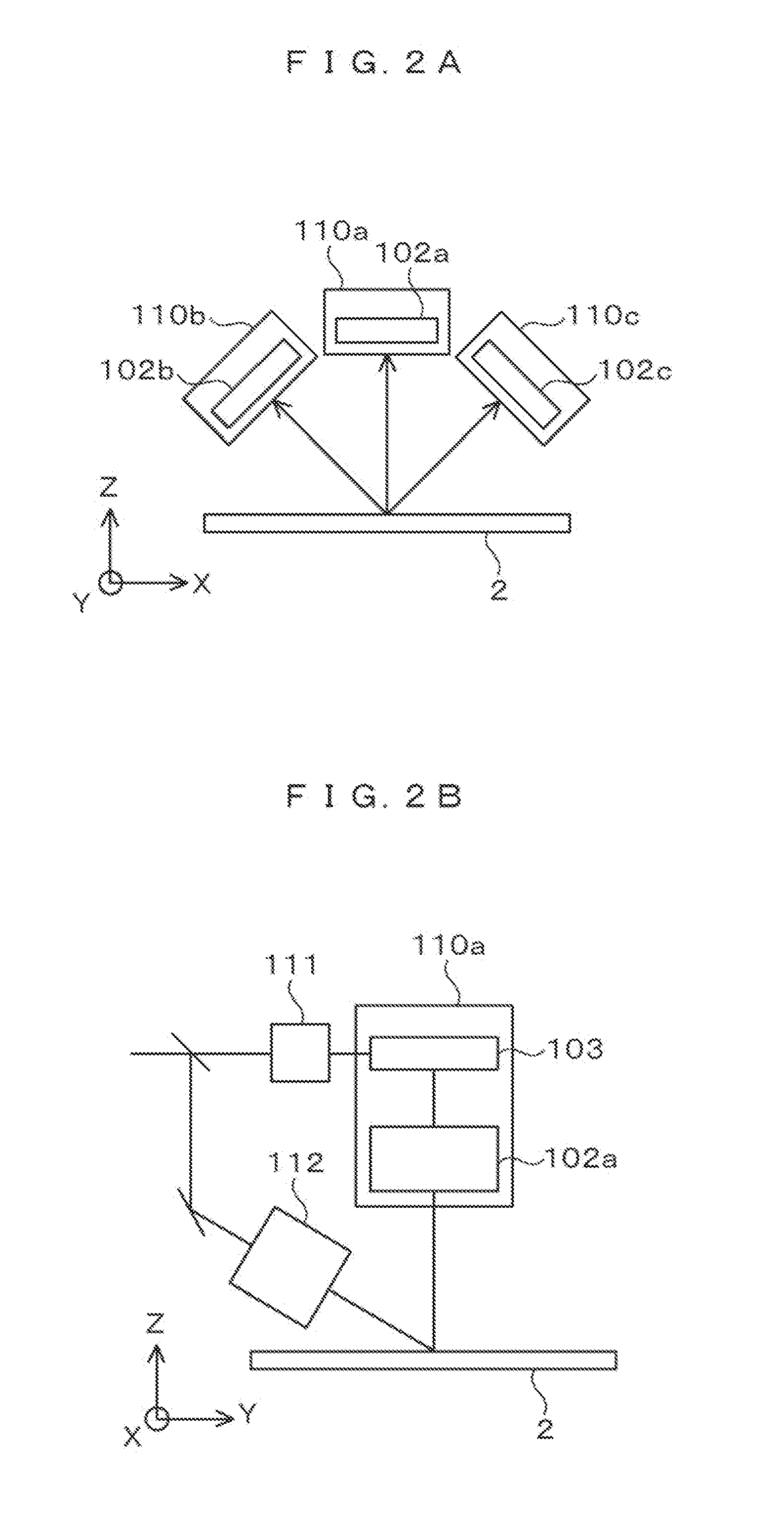
[0038]Inspection of a bridge defect (where parts of an L & S pattern of a high aspect ratio and a short interval (shorter than or equal to the wavelength of the illuminating light) are connected together) with high sensitivity is made possible by employing an illumination optical system and a detection optical system having the following features for the defect inspection device: The illumination optical system condenses light into a linear shape that is long in ...


PUM


Abstract

To detect a bridge defect between lines of a line pattern formed on a sample at pitches narrower than the wavelength of inspection light, a defect inspection device is configured to comprise: a light source which emits laser; a vertical illumination unit which applies the laser to the sample from a vertical direction via an objective lens by converting the laser into linearly polarized light by using a polarization conversion unit in a state polarized in a direction orthogonal to the longitudinal direction of the line pattern; an oblique illumination unit which applies the laser to the sample from an oblique direction; a detection optical unit including an optical filter which selectively transmits a scattered light component from the defect by converting the polarization state of the reflected/scattered light; and a signal processing unit which detects the defect on the sample by processing a detection signal.

Description

CLAIM OF PRIORITY[0001]The present application claims priority from Japanese Patent Application JP 2014-62440 filed on Mar. 25, 2014, the content of which is hereby incorporated by reference into this application.BACKGROUND OF THE INVENTION[0002]1. Field of the Invention[0003]The present invention relates to a defect inspection method and a defect inspection device for inspecting the status of occurrence of defects in a manufacturing process for manufacturing a product by forming a pattern on a substrate (semiconductor manufacturing process, liquid crystal display element manufacturing process, printed circuit board manufacturing process, etc.) to be used in a process for detecting the defects, analyzing the occurrence of defects and taking countermeasures against the occurrence of defects.[0004]2. Description of the Related Art[0005]A background technology of this technical field is described in JP-A-2008-39882 (Patent Document 1). In Patent Document 1, light caused by incidence of...

Claims


Application Information

Patent Timeline
IPC IPC(8): G01N21/956G01N21/95G01N21/21
CPCG01N21/956G01N21/21G01N2201/06113G01N2021/9513G01N21/9501G01N21/95607G01N2021/8848G01N2021/95638
Inventor URANO, YUTAHONDA, TOSHIFUMISHIBATA, YUKIHIRO
Owner HITACHI HIGH-TECH CORP
Why Eureka
Try Eureka