Fuel cell module

Active Publication Date: 2015-10-01
HONDA MOTOR CO LTD
View PDF8 Cites 2 Cited by
  • Summary
  • Abstract
  • Description
  • Claims
  • Application Information

AI Technical Summary

Benefits of technology

The present invention aims to provide a fuel cell module with a simple and compact structure that improves heat efficiency and facilitates thermally self-sustaining operation. It suppresses heat waste and radiation, and achieves a higher operating temperature using only heat energy generated by the fuel cell. The fuel cell module is designed to be easy to install and maintain.

Problems solved by technology

Therefore, the quantity of heat for raising the temperature of the oxygen-containing gas supplied to the fuel cell stack 1a tends to be inefficient, and the efficiency is low.
Therefore, considerably high pressure losses tend to occur.
Therefore, heat cannot be recovered, and the efficiency is low.

Method used


Image

  • Fuel cell module
  • Fuel cell module
  • Fuel cell module

Examples


Embodiment Construction

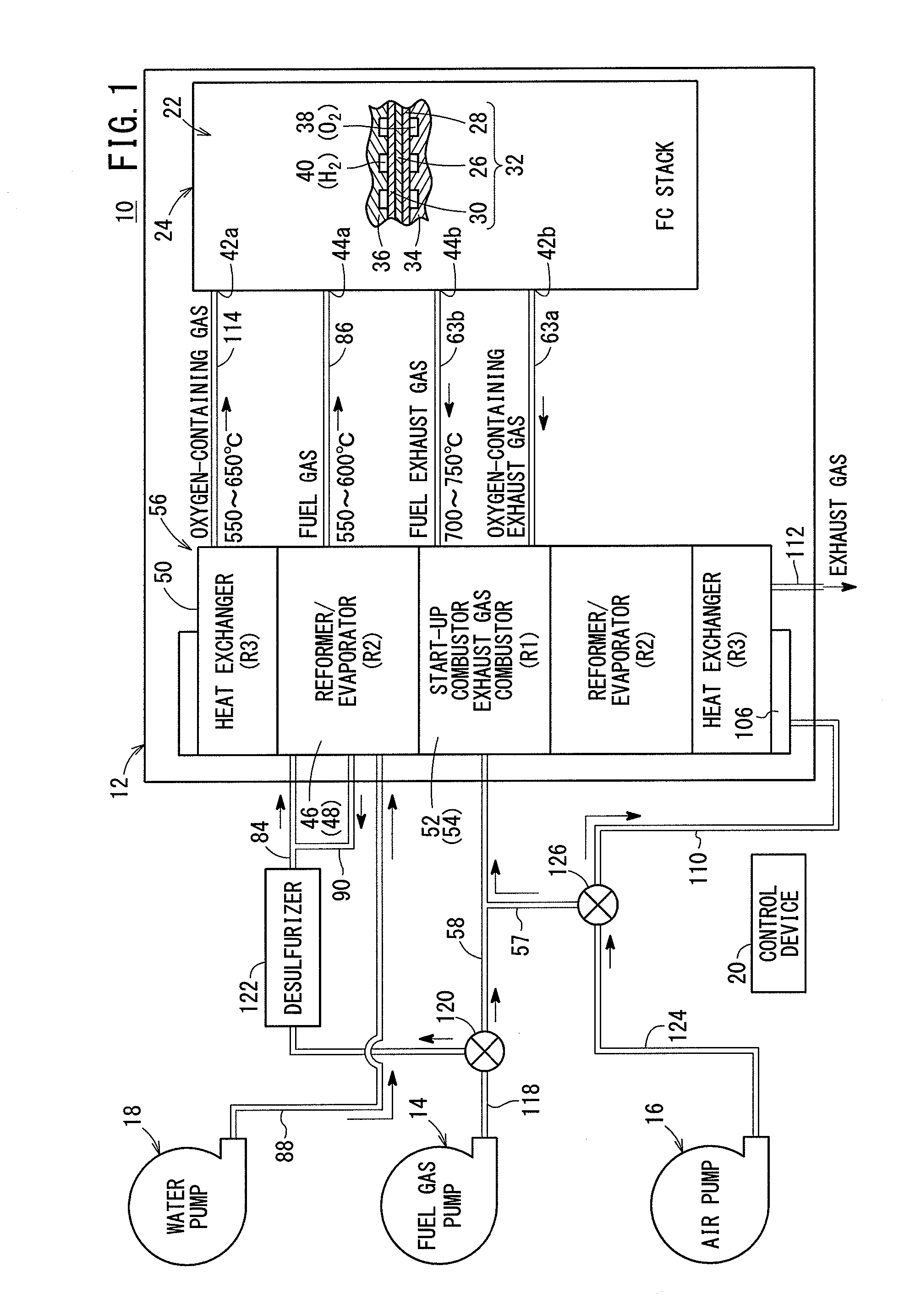
[0030]As shown in FIG. 1, a fuel cell system 10 includes a fuel cell module 12 according to an embodiment of the present invention, and the fuel cell system 10 is used in various applications, including stationary and mobile applications. For example, the fuel cell system 10 is mounted on a vehicle.

[0031]The fuel cell system 10 includes the fuel cell module (SOFC module) 12 for generating electrical energy in power generation by electrochemical reactions of a fuel gas (a gas produced by mixing a hydrogen gas, methane, and carbon monoxide) and an oxygen-containing gas (air), a raw fuel supply apparatus (including a fuel gas pump) 14 for supplying a raw fuel (e.g., city gas) to the fuel cell module 12, an oxygen-containing gas supply apparatus (including an air pump) 16 for supplying the oxygen-containing gas to the fuel cell module 12, a water supply apparatus (including a water pump) 18 for supplying water to the fuel cell module 12, and a control device 20 for controlling the amoun...


PUM


Abstract

A fuel cell module includes a first area where an exhaust gas combustor and a start-up combustor are provided, an annular second area around the first area and where a reformer and an evaporator are provided, and an annular third area around the second area and where a heat exchanger is provided. The exhaust gas combustor and the start-up combustor are provided coaxially with and separately away from each other

Description

TECHNICAL FIELD[0001]The present invention relates to a fuel cell module including a fuel cell stack formed by stacking a plurality of fuel cells for generating electricity by electrochemical reactions of a fuel gas and an oxygen-containing gas.BACKGROUND ART[0002]Typically, a solid oxide fuel cell (SOFC) employs a solid electrolyte of ion-conductive solid oxide such as stabilized zirconia. The solid electrolyte is interposed between an anode and a cathode to form an electrolyte electrode assembly (hereinafter also referred to as MEA). The electrolyte electrode assembly is sandwiched between separators (bipolar plates). In use, generally, predetermined numbers of the electrolyte electrode assemblies and the separators are stacked together to form a fuel cell stack.[0003]As a system including this type of fuel cell stack, for example, a fuel cell battery disclosed in Japanese Laid-Open Patent Publication No. 2001-236980 (hereinafter referred to as the conventional technique 1) is kno...

Claims


Application Information

Patent Timeline
IPC IPC(8): H01M8/06
CPCH01M8/0618H01M2300/0074H01M2008/1293B01J8/067B01J2208/00194B01J2208/00203B01J2208/00504B01J2208/0053B01J2208/00716C01B3/384C01B2203/0233C01B2203/066C01B2203/1288C01B2203/82H01M8/04022H01M8/04074H01M8/04268H01M8/0631Y02E60/50
Inventor YOSHIMINE, YUKIYAMAMOTO, JUN
Owner HONDA MOTOR CO LTD
Why Eureka
Try Eureka