Image capturing apparatus and inspection apparatus and inspection method

a technology of image capture and inspection apparatus, which is applied in the direction of image enhancement, instruments, television systems, etc., can solve the problems of reducing the production yield of semiconductor elements, reducing inspection accuracy, and prolonging inspection tim

Active Publication Date: 2015-10-08
NUFLARE TECH INC
View PDF9 Cites 8 Cited by
  • Summary
  • Abstract
  • Description
  • Claims
  • Application Information

AI Technical Summary

Benefits of technology

[0013]According to one aspect of the present invention, an imaging capturing apparatus includes a light source, a polarizing beam splitter configured to illuminate a target with light from the light source, a sensor configured to capture an image of the inspection target by incidence of light reflected from the target through the polarizing beam splitter, and a Faraday rotator provided between the polarizing beam splitter and the target and disposed away from the polarizing beam splitter such that a Faraday rotation angle in the polarizing beam splitter is within a range of an angle equal to or larger than −0.5 degrees and an angle equal to or smaller than 0.5 degrees.
[0014]According to another aspect of the present invention, an inspection apparatus includes an illumination optical system including a light source configured to emit light having a predetermined wavelength, a polarization beamsplitter which reflects the light emitted from the light source, a half-wavelength plate which transmits the light reflected by the polarization beamsplitter, and a Faraday rotator which is configured between the half-wavelength plate and a sample which is an inspection target and transmits the light transmitted through the half-wavelength plate, configured to illuminate the sample by the light including a polarization plane having an angle except an angle within a range of an angle equal to or larger than −0.5 degrees and an angle equal to or smaller than 0.5 degrees, and a range of an angle equal to or larger than −85 degrees and an angle equal to or smaller than 95 degrees with respect to a repetitive direction of a repetitive pattern formed in the sample, a sensor configured to capture an optical image of a pattern formed in the sample, an imaging optical system configured to form an image of the light reflected by the sample onto the sensor by causing the light to be transmitted through the half-wavelength plate, the Faraday rotator, and the polarization beamsplitter, an image processor configured to obtain a gradation value in each pixel with respect to the optical image and acquire
[0015]The predetermined wavelength of the light from the light source and a numerical aperture of an objective lens through which the sample is illuminated with the light transmitted through the Faraday rotator defines a resolution limit. The resolution limit is a value at which the pattern is not resolved. The Faraday rotator is disposed away from the polarizing beam splitter s

Problems solved by technology

A defect of a circuit pattern formed on of a mask or template can be cited as a large factor that reduces a production yield of the semicon

Method used


Image

  • Image capturing apparatus and inspection apparatus and inspection method
  • Image capturing apparatus and inspection apparatus and inspection method
  • Image capturing apparatus and inspection apparatus and inspection method

Examples


Embodiment Construction

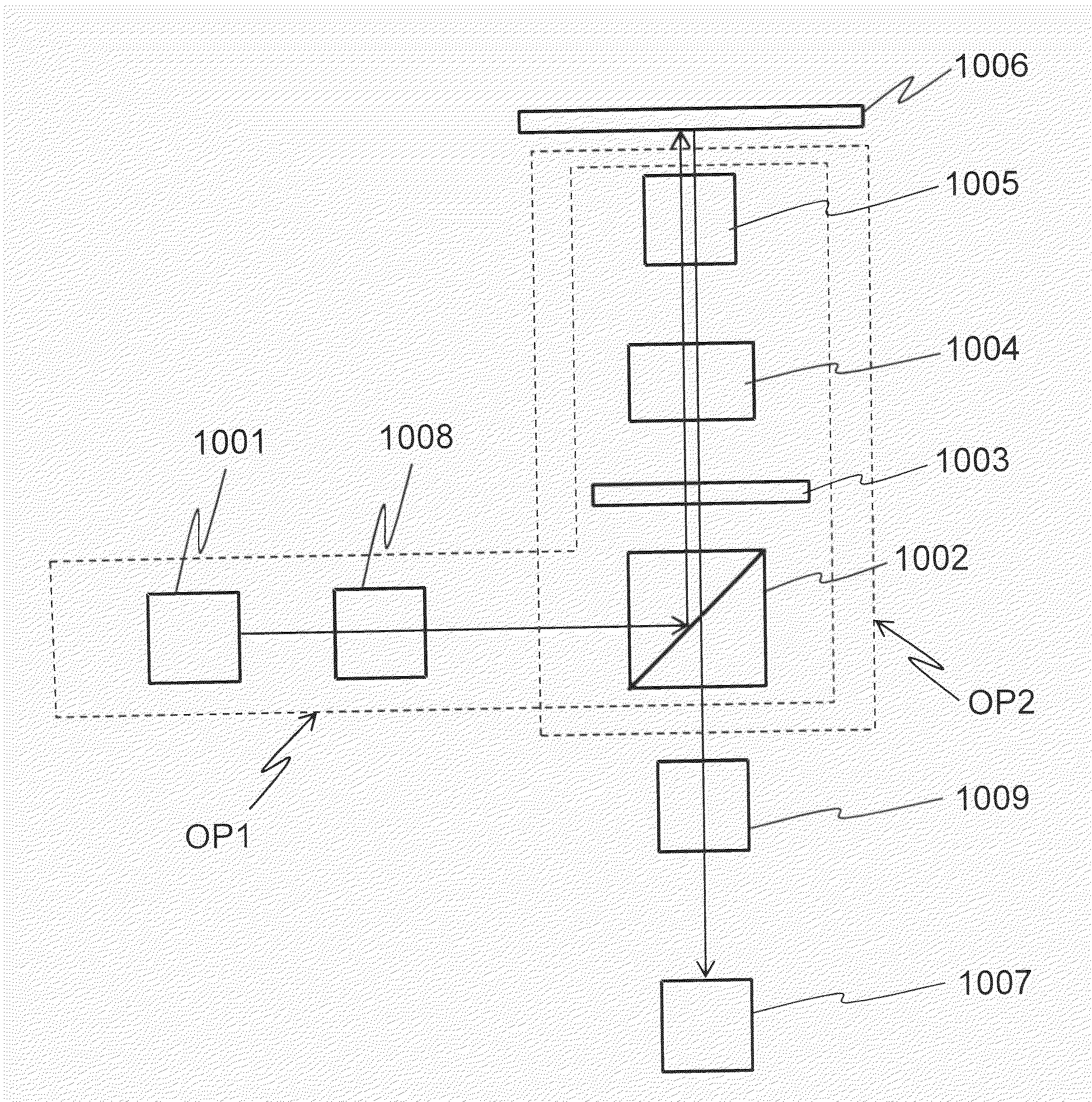
[0034]FIG. 1 illustrates an example of a configuration of an image capturing apparatus according to the present embodiment. The image capturing apparatus includes an illumination optical system OP1 that illuminates a mask 1006, a sensor 1007 that captures an image of a pattern of the mask 1006, and an imaging optical system OP2 that images the light reflected from the mask 1006 onto the sensor 1007.

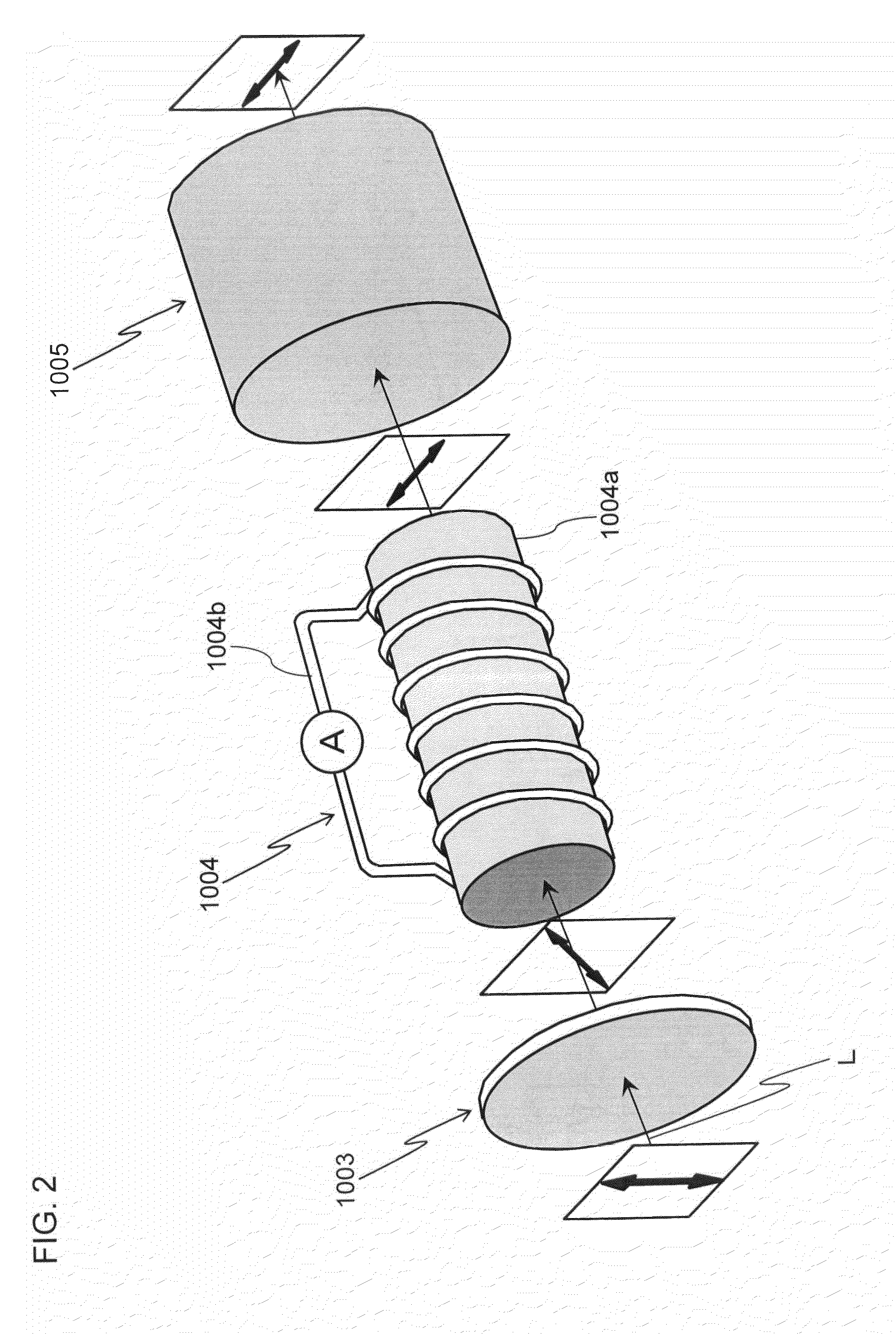
[0035]The illumination optical system OP1 includes a light source 1001, a beam shaping optical system 1008, a polarization beamsplitter 1002, a half-wavelength plate 1003, a Faraday rotator 1004, and an objective lens 1005. The beam shaping optical system 1008 includes an expander lens that expands a beam, an integrator lens that increases the uniformity of the light to the surface, and a relay lens in which a magnification is set such that a mask surface is illuminated with the beam of a desired size.

[0036]The imaging optical system OP2 includes the objective lens 1005, the Faraday rotat...


PUM


Abstract

An imaging capturing apparatus comprising, a light source, a polarizing beam splitter configured to illuminate a target with light from the light source, a sensor configured to capture an image of the inspection target by incidence of light reflected from the target through the polarizing beam splitter, and a Faraday rotator provided between the polarizing beam splitter and the target and disposed away from the polarizing beam splitter such that a Faraday rotation angle in the polarizing beam splitter is within a range of an angle equal to or larger than −0.5 degrees and an angle equal to or smaller than 0.5 degrees.

Description

CROSS-REFERENCE TO THE RELATED APPLICATION[0001]The entire disclosure of Japanese Patent Application No. 2014-078090, filed on Apr. 4, 2014, and 2015-073512 filed on Mar. 31, 2015, including specifications, claims, drawings, and summaries, on which the Convention priority of the present application is based, are incorporated herein in their entirety.FIELD OF THE INVENTION[0002]The present invention relates to an Image Capturing Apparatus and an Inspection Apparatus and Inspection Method.[0003]Recently, with an increasing integration degree of a semiconductor device, the dimensions of individual elements have become finer, and the widths of wiring and gate constituting each element have also become finer.[0004]A process of transferring an original plate (known as a mask or a reticle, hereinafter collectively referred to as a mask) to a photosensitive resin to fabricate a wafer is fundamental to the production of a semiconductor integrated circuit. Repeating this fundamental process p...

Claims


Application Information

Patent Timeline
IPC IPC(8): G01N21/88G06T7/00G01N21/95
CPCG01N21/8806G01N21/9501G06T7/0008G06T2207/30148G01N2201/0636G01N2201/06113G06T2207/10152G01N2201/0683G02B21/0016G02B27/283G02B27/286G01N21/956G01N2021/8848G01N2021/95676
Inventor OGAWA, RIKI
Owner NUFLARE TECH INC
Why Eureka
Try Eureka