Regenerative optical amplifier for short pulsed lasers, a laser source and a laser workstation

a regenerative optical amplifier and laser technology, applied in the direction of laser optical devices, laser details, optical resonator shape and construction, etc., can solve the problems of increasing the prime cost of the regenerative amplifier, the rotation or change of the polarization state of the seed wave, and the inability of the electro-optical element to work

Active Publication Date: 2015-10-08
UAB MGF SVIESOS KONVERSIJA
View PDF0 Cites 13 Cited by
  • Summary
  • Abstract
  • Description
  • Claims
  • Application Information

AI Technical Summary

Benefits of technology

[0011]In order to eliminate the drawbacks indicated above, this invention provides a solution for operating a regenerative amplifier using single electro-optical device (2), such as Pockels cell. An efficient cavity geometry of a regenerative amplifier is provided for enabling pulse selection, locking and releasing to the output by operating a single Pockels cell unit placed essentially in the middle of the cavity. One side of the cavity, with respect to the location of said Pockels cell, is preferably an empty space, whereas the other side is provided with a gain medium, which is pumped by a pump source. In another embodiment, gain medium can be arranged in both optical paths (12, 13).

Problems solved by technology

Absence of voltage means that the electro-optical element is not working, while application of voltage results in rotation or change of polarization state of a seed wave.
Using several Pockels cells significantly increases the prime cost of the regenerative amplifier.
Synchronization, simultaneous control of several electro-optical devices and monitoring makes the control electronics more complex.
Extra heat is generated by the driving circuitry of the additional Pockels cell running at high repetition rates, which reduces the efficiency of the laser system.
A drawback of such optical design is that some losses of the pulse energy occur, when the amplified pulse passes the Pockels cell on the output of the RA, as well as excess heat is generated in the crystal of the Pockels cell.
Such layout is rather inefficient and might cause additional distortions of the beam or pulse shape.

Method used


Image

  • Regenerative optical amplifier for short pulsed lasers, a laser source and a laser workstation
  • Regenerative optical amplifier for short pulsed lasers, a laser source and a laser workstation
  • Regenerative optical amplifier for short pulsed lasers, a laser source and a laser workstation

Examples


example 1

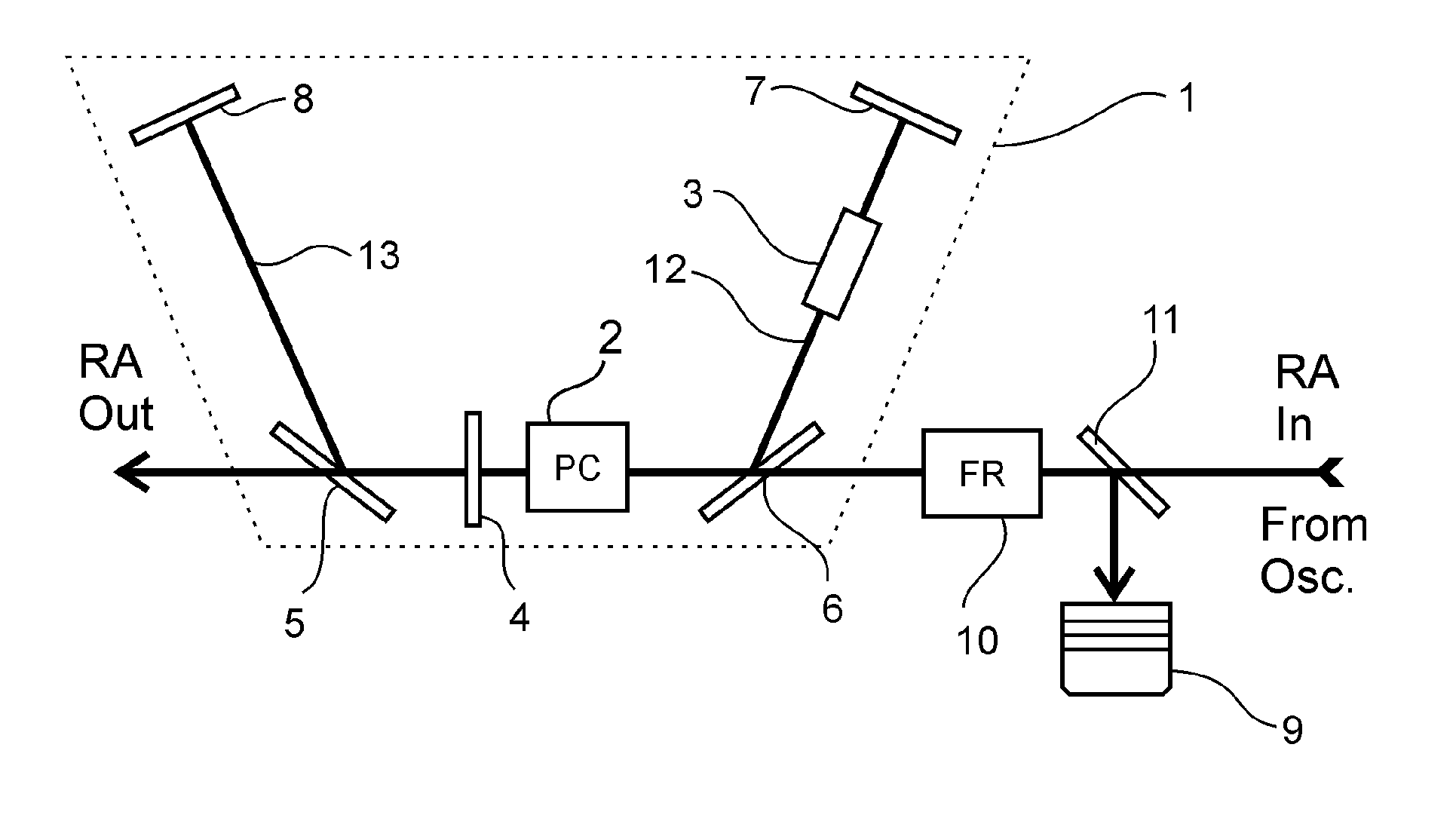
[0029]As illustrated in FIG. 1, in this example of a preferred embodiment, the RA input, the Pockels Cell (2), polarizers (5, 6), the half-wave plate (4) and the RA Out are arranged essentially in a row. For the sake of simplicity, herein and further, the polarization of the input seed pulse train will be referred to as ‘p polarization’ and a switched polarization, which is essentially perpendicular to the p polarization, will be called ‘s polarization’.

[0030]The first polarizer (5), which is arranged on the output side with respect to the PC unit (2), is oriented such, that it reflects the s polarization. Whenever the PC unit (2) is not activated and is not changing the polarization state of seed pulses coming from the oscillator, the polarization state of the seed pulse is rotated only by the half-wave plate from p to s and then reflected by the first polarizer (5) towards the second optical path (13).

[0031]In this exemplary embodiment, when a seed pulse remains unamplified, RA op...

example 2

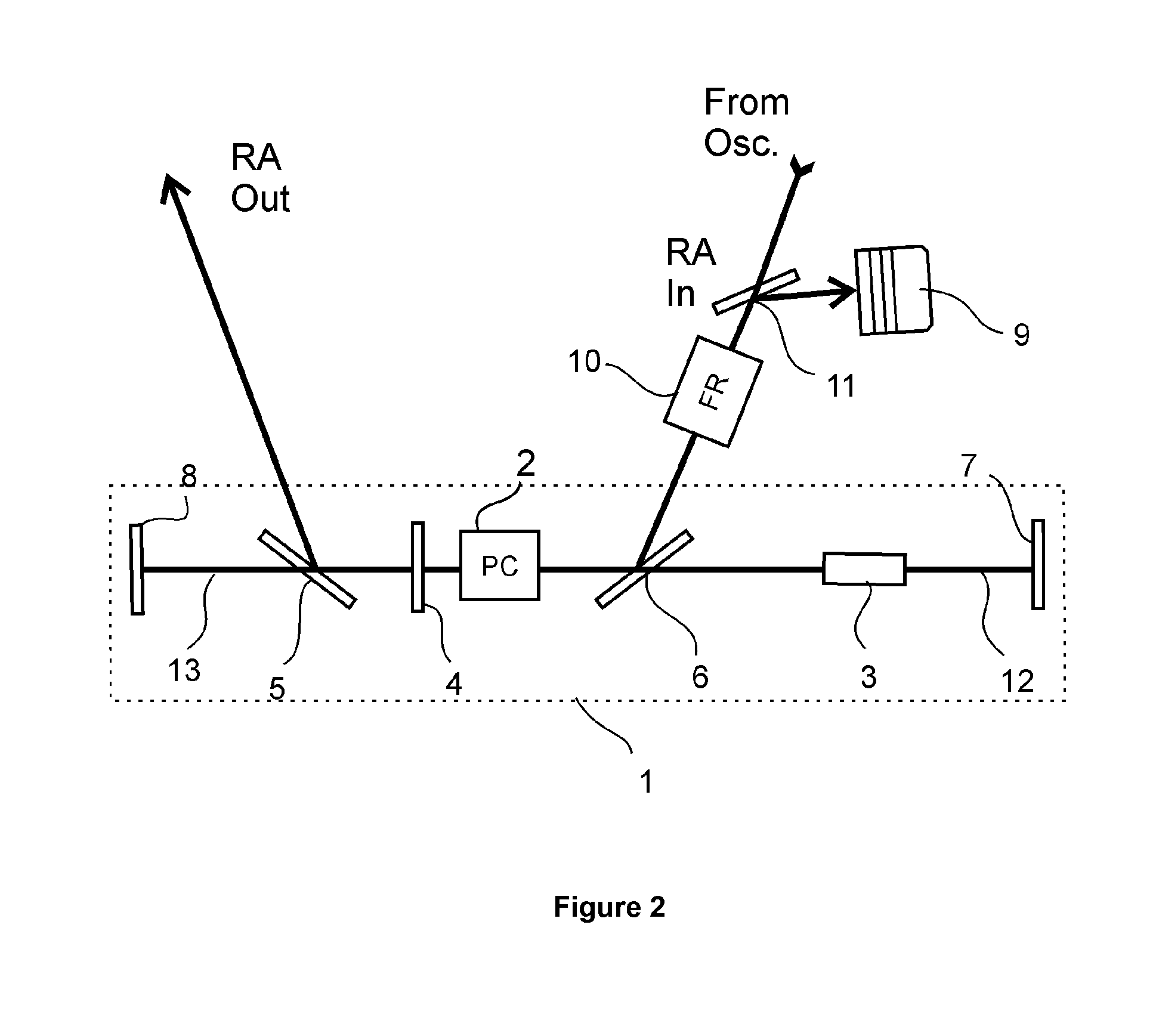
[0054]FIG. 2 illustrates another exemplary embodiment, wherein the RA cavity (1) is essentially of linear geometry. It should be understood that the optical paths (12, 13) can be of significant length and thus it might be required to arrange additional mirrors in said optical paths (12, 13) in order to fold the optical paths and make them more compact. The same is applicable to Example 1 and the optical layout illustrated in FIG. 1. The RA input and output sections are arranged such, that the seed pulses are coupled in the RA cavity (1) and the amplified pulses are out-coupled by reflection from the polarizers (5, 6).

[0055]In this exemplary embodiment, when a pulse is amplified, RA operation comprises following steps:

[0056]Additional pulse picker PC unit may be used when extremely high contrast pulses are required[0057]I. the seed pulse of p polarization reflects from the second polarizer (6) towards the Pockels cell (2);[0058]II. the polarization state is changed to s only by the h...


PUM


Abstract

This invention provides a solution for operating a regenerative amplifier using a single electro-optical device, such as a Pockels cell. An efficient cavity geometry of a regenerative amplifier is provided for enabling pulse selection, coupling and releasing to an output by operating a single Pockels cell unit placed essentially in the middle of the optical cavity, between two polarizers, whereas a first polarizer is used for release of an amplified pulse and a second polarizer is used for injection of seed pulses and release of at least one of waste amplified pulses and seed pulses. One side of the cavity, with respect to the location of said Pockels cell, includes an empty space, whereas the other side is provided with a gain medium, which is pumped by a pump source. The regenerative amplifier of such optical design is both efficient and cost effective. The single electro-optical unit works both as the control unit for operating the regenerative amplifier and as an output pulse picker unit.

Description

FIELD OF INVENTION[0001]The invention relates to regenerative optical amplifiers comprising a cavity for amplifying short pulses of light and a voltage-driven electro-optical unit for controlling the operation of the optical amplifier.BACKGROUND OF INVENTION[0002]Regenerative amplifiers (RA) are used to amplify optical signals in order to increase pulse energy. Optical signals to be amplified are transmitted and locked inside regenerative amplifier by means of switching electro-optical elements, such as Pockels cells, driven by high voltage, typically in the kilovolt range. Said input optical signals are referred to as seed pulses.[0003]The gain media inside RA is pumped by a light source, such as laser diodes or flash lamps. The pump radiation excites atoms inside the gain medium and passing seed pulses induce stimulated emission of radiation and thus are amplified.[0004]In conventional RA designs, polarizing electro-optical elements, such as Pockels cells are arranged inside a res...

Claims


Application Information

Patent Timeline
Patent Type & Authority Applications(United States)
IPC IPC(8): H01S3/23H01S3/107H01S3/117H01S3/08H01S3/115H01S3/10H01S3/094
CPCH01S3/235H01S3/10023H01S3/107H01S3/117H01S3/094076H01S3/08054H01S3/115H01S3/10061H01S3/005H01S3/0064H01S3/0816H01S3/0915H01S3/1003H01S3/10046H01S3/101
Inventor DANIELIUS, ROMUALDAS
Owner UAB MGF SVIESOS KONVERSIJA
Why Eureka
Try Eureka