Mosfet switch circuit for slow switching application

a switch circuit and switch circuit technology, applied in the direction of pulse technique, process and machine control, instruments, etc., can solve problems such as permanent device failur

Active Publication Date: 2015-10-15
ALPHA & OMEGA SEMICON INC
View PDF8 Cites 19 Cited by
  • Summary
  • Abstract
  • Description
  • Claims
  • Application Information

AI Technical Summary

Benefits of technology

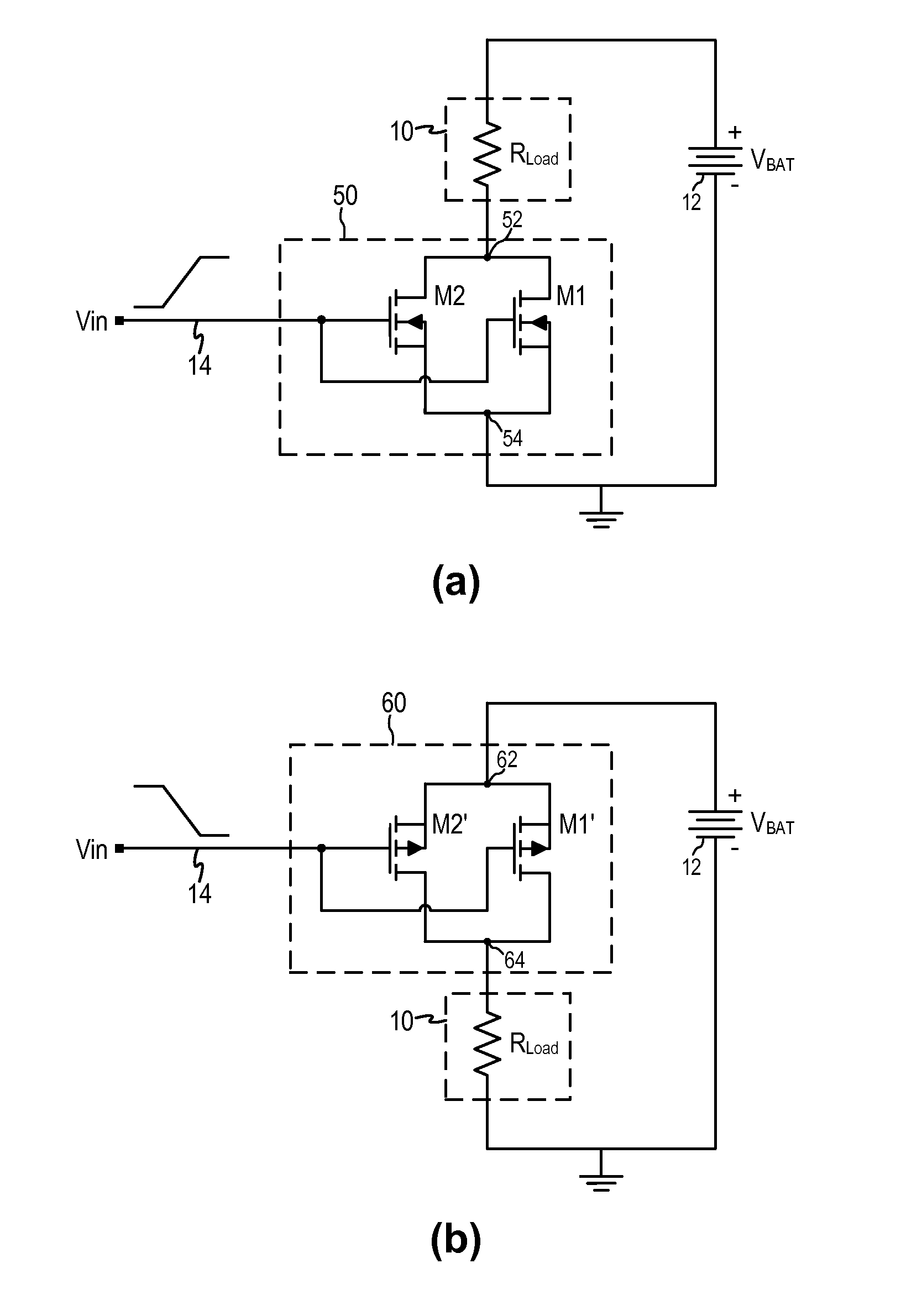
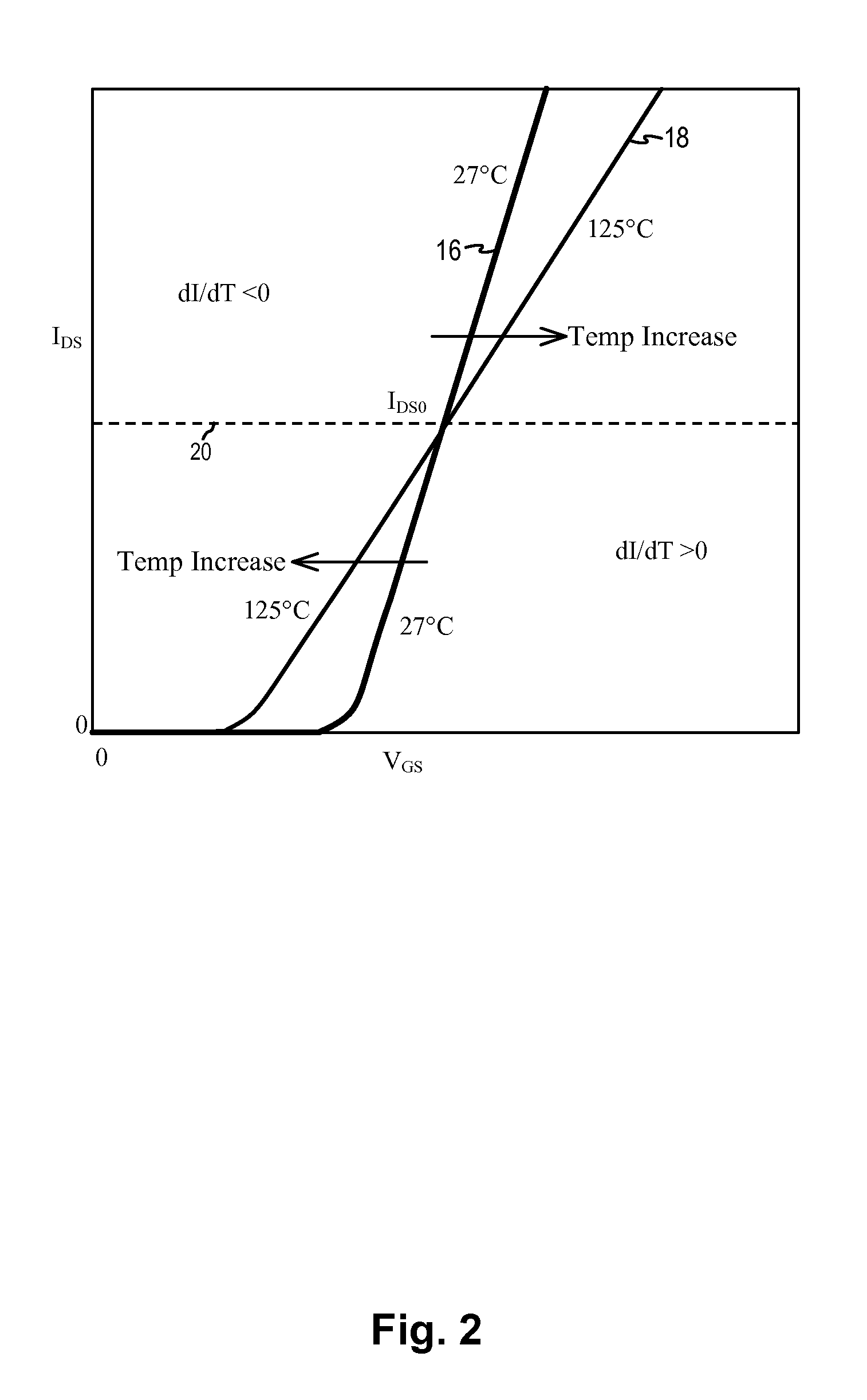
[0036]The load switch circuit of the present invention realizes many advantages over conventional load switch circuit. First, the load switch circuit of the present invention ensures thermal stability by using a pair of parallel connected MOSFET device with one MOSFET device being operated in the thermally stable region above the drain current crossover point during the control signal ramping up period. The second, larger MOSFET device is turned on only after the drain voltage is pulled down so that thermal runaway is avoided. Second, the load switch circuit uses a small MOSFET with high on-resistance during the initial ramping period and then uses a larger MOSFET with low on-resistance in parallel for normal load switch operation. Thus, the load switch circuit has only a small area penalty due to transistor M1 but the load switch circuit can operate at a low on-resistance as desired. Lastly, the load switch circuit of the present invention allows for ease of implementation where the threshold voltages and the area ratios of transistors M1 and M2 can be selected to optimize the load switch circuit operation and the power dissipation for different applications.

Problems solved by technology

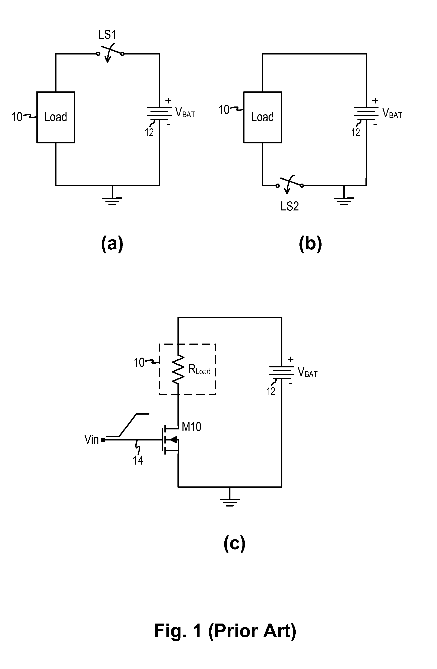
However, as the gate voltage of the load switch transistor M10 ramps up, the transistor may be biased in the saturation region or linear mode for a long time.
Excessive heating at the load switch may result in thermal runaway during the control voltage ramp up time, resulting in permanent device failure.

Method used


Image

  • Mosfet switch circuit for slow switching application
  • Mosfet switch circuit for slow switching application
  • Mosfet switch circuit for slow switching application

Examples


Embodiment Construction

[0014]The invention can be implemented in numerous ways, including as a process; an apparatus; a system; and / or a composition of matter. In this specification, these implementations, or any other form that the invention may take, may be referred to as techniques. In general, the order of the steps of disclosed processes may be altered within the scope of the invention.

[0015]A detailed description of one or more embodiments of the invention is provided below along with accompanying figures that illustrate the principles of the invention. The invention is described in connection with such embodiments, but the invention is not limited to any embodiment. The scope of the invention is limited only by the claims and the invention encompasses numerous alternatives, modifications and equivalents. Numerous specific details are set forth in the following description in order to provide a thorough understanding of the invention. These details are provided for the purpose of example and the inv...


PUM


Abstract

A switch circuit includes a first MOS transistor and a second MOS transistor of a same conductivity type connected in parallel between a first terminal and a second terminal. The first and second MOS transistors have respective gate terminals coupled to the control terminal to receive a control signal to turn the switch circuit on or off where the control signal transitions from a first voltage level to a second voltage level at a slow rate of change. The first MOS transistor has a first threshold voltage and the second MOS transistor has a second threshold voltage where the first threshold voltage is less than the second threshold voltage

Description

BACKGROUND OF THE INVENTION[0001]Portable electronic devices are incorporating load switches to implement power management functions. In particular, there is a need in portable electronic devices to extend battery life while maintaining performance level. Load switches are used in portable electronic devices to enable the system to make power management decisions based on the peripherals or sub-circuits currently being used. When incorporated in an electronic device, a load switch is controlled by the electronic device to connect or disconnect a voltage rail to a specific load. The load switch provides a means to power a load when it is in demand so as to allow the electronic device to maximize performance.[0002]A load switch circuit is typically implemented using a switching device controlled by an on-off control signal. The switching device is typically a MOSFET (metal-oxide-semiconductor field-effect-transistor) device that passes the supply voltage to a specific load when the tr...

Claims


Application Information

Patent Timeline
Patent Type & Authority Applications(United States)
IPC IPC(8): H02M3/158
CPCH02M3/158H01L21/8234H01L27/088H03K17/164
Inventor LUI, SIK K.NG, DANIEL S.WANG, XIAOBIN
Owner ALPHA & OMEGA SEMICON INC
Why Eureka
Try Eureka