CSF shunt flow evaluation apparatus and method using a conformable expanded dynamic range thermosensor

a dynamic range thermosensor and flow evaluation technology, applied in the field of cerebrospinal fluid (csf) shunts, can solve the problems of shunt failure, progressive neurological dysfunction and death, and shunt failure is still almost inevitable during a patient's life,

Active Publication Date: 2015-10-29
SHUNTCHECK
View PDF14 Cites 3 Cited by
  • Summary
  • Abstract
  • Description
  • Claims
  • Application Information

AI Technical Summary

Benefits of technology

[0049]FIG. 17C is an exemplary display screen showing a patient's temperature sensor data that a ShuntCheck flow algorithm w...

Problems solved by technology

Untreated hydrocephalus leads to progressive neurological dysfunction and death.
However, shunt failure is still almost inevitable during a patient's life.
Obstruction of the ventricular catheter, usually from tissue ingrowth or clots, is overwhelmingly the greatest cause of shunt failure.
However, since catheter replacement surgery carries risks of life-threatening complications such as infection or embolism, a need for shunt revision needs to be reasonably established.
The problem is that the usual clinical manifestations of shunt failure, such as headaches, vomiting, or loss of vision, are non specific and are difficult to differentiate from common, less serious illnesses, particularly in pediatric patients.
An unacceptably high number of hydrocephalic children still die as a result of shunt malfunction, primarily because of a failure to identify shunt blockage at an early stage.
The early diagnosis of shunt obstruction is complex and difficult.
While a number of shunt flow detection methods are available, none are diagnostic when used alone or are without complication, and there is little standardization to guide physicians in their interpretation (Table 1).
Physical examination of the patient, including pumping of the shunt reservoir, is unreliable.
Measuring CSF pressure by “shunt tap” is inv...

Method used


Image

  • CSF shunt flow evaluation apparatus and method using a conformable expanded dynamic range thermosensor
  • CSF shunt flow evaluation apparatus and method using a conformable expanded dynamic range thermosensor
  • CSF shunt flow evaluation apparatus and method using a conformable expanded dynamic range thermosensor

Examples


Embodiment Construction

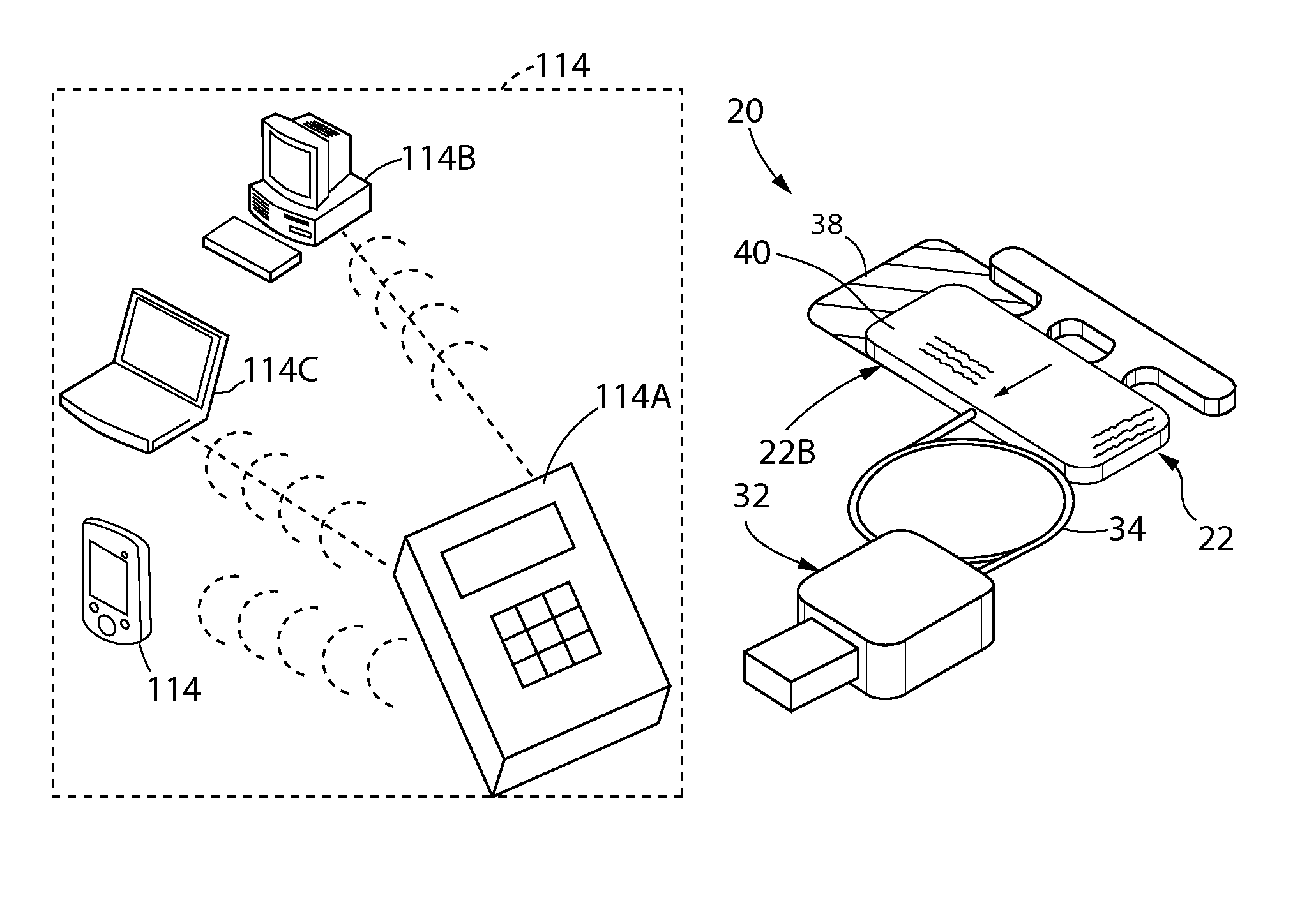
[0050]As shown most clearly in FIG. 4, the present invention 20 comprises an extended dynamic range (EDR) thermosensor 22 which is coupled to a sensor processing device 114. By way of example only, the sensor processing device 114 may comprise a data acquisition unit (DAQ) 114A that converts and conditions analog temperature sensor signals into digital format for use with, by way of example only, a workstation 114B, a laptop / tablet computer 114C, or hand-held computer device (e.g., personal digital assistant, PDA), or any known computer known in the art, etc., either wired or wirelessly, running ShuntCheck software which analyzes temperature data from the temperature sensors and provides a time-temperature graph and a flow or no-flow result. Although FIG. 4 shows the DAQ 114A relaying the data to the other computer devices, it should be understood that it within the broadest scope of the invention 20 that the DAQ may comprise the ShuntCheck software thereby collecting and analyzing ...


PUM


Abstract

An apparatus and method that utilizes thermal dilution to detect a wide range of flow rates and/or flow status in cerebrospinal fluid (CSF) shunt systems. The use of a large cold source in combination with thermosensor pad of a particular construction provide a fluid flow analyzer with the ability to detect very low levels of CSF flow. In addition, a method for adjusting thermal dilution readings to compensate for varying shunt catheter depth is shown and for determining a steady state of the thermal dilution readings. The thermosensor pad is conformable to a patient's skin contour thereby making the apparatus and method less sensitive to ambient temperature errors and, as a result, more accurate in assessing CSF flow. Furthermore, a software error check is provided for identifying poor sensor-to-skin contact for alerting an operator to re-apply the thermosensor pad to correct, as well as a post-test check to determine if temperature data is reasonable before determining flow status or flow rate.

Description

CROSS-REFERENCE TO RELATED APPLICATIONS[0001]This PCT application claims the benefit under 35 U.S.C. §119(e) of Provisional Application Ser. No. 61 / 797,389 filed on Dec. 6, 2012 entitled EXPANDED DYNAMIC RANGE CSF SHUNT FLOW THERMOSENSOR AND TEST PACK and also claims the benefit under 35 U.S.C. §119(e) of Provisional Application Ser. No. 61 / 960,026 filed on Sep. 9, 2013 entitled CONFORMABLE EXPANDED DYNAMIC RANGE CSF SHUNT FLOW THERMOSENSOR and all of whose entire disclosures are incorporated by reference herein.BACKGROUND OF THE INVENTION[0002]1. Field of Invention[0003]This present invention generally relates to cerebrospinal fluid (CSF) shunts and, more particular, to a device and method for testing for the presence, absence and / or rate of CSF flow through shunt tubing implanted under the skin in hydrocephalus patients.[0004]2. Description of Related Art[0005]Hydrocephalus is a condition of abnormal cerebrospinal fluid (CSF) homeostasis, resulting in an accumulation of CSF in the...

Claims


Application Information

Patent Timeline
IPC IPC(8): A61B5/01A61M27/00
CPCA61M27/006A61B5/01A61B5/6833A61B5/684A61B5/015A61B5/14507A61B5/031A61B5/032A61B2562/0271A61B2562/043
Inventor FRITZ, FREDERICK J.SWOBODA, MAREKMATTIUCCI, MARK E.HOCHMAN, MATIAS G.
Owner SHUNTCHECK
Why Eureka
Try Eureka