Method and apparatus for simulating blood flow under patient-specific boundary conditions derived from an estimated cardiac ejection output

a technology of blood flow and boundary conditions, applied in the field of simulation of blood flow, can solve the problem that the impact of three-dimensional (3d) blood flow cannot be fully assessed by such 2d measurements, and achieve the effect of facilitating process automation

Inactive Publication Date: 2015-11-05
KONINKLJIJKE PHILIPS NV
View PDF2 Cites 9 Cited by
  • Summary
  • Abstract
  • Description
  • Claims
  • Application Information

AI Technical Summary

Benefits of technology

[0010]Thus, blood flow through a patient-specific geometry of a target cardiovascular structure under patient-specific boundary conditions is derived from the cardiac ejection output per heart stroke. The result of the simulation yields objective values for physiologically relevant parameters such as one or more of pressure drop, average blood residence time, flow rate, wall sheer stress and blood swirl in said cardiovascular structure. According to a first aspect, a modeling circuit may be provided for generating the volumetric mesh of the cardiovascular structure based on a partitioned segmented digital image of the cardiovascular structure. Thereby, the volumetric mesh can be directly generated and does not need to be derived or loaded from a remote device or network.According to a second aspect which can be combined with the above first aspect, the digital image may be a CT image or an MM image or an ultrasonic image. Thus, the proposed solution can be used for a wide range of medical imaging systems.According to a third aspect which can be combined with the above first or second aspect, the digital image may be partitioned by using a model-based segmentation to obtain a surface mesh of the target cardiovascular structure. Thereby, the volumetric mesh can be readily obtained by converting or transforming the surface mesh into the volumetric mesh.
[0011]According to a fourth aspect which can be combined with any one of the above first to third aspects, the simulation may be done by computational fluid dynamics (CFD) or fluid-solid interaction (FSI) simulation. This facilitates automation of the process of creating computer models.According to a fifth aspect which can be combined with any one of the above first to fourth aspects, the cardiac ejection output per heart stroke may be estimated based on electrocardiography (ECG) gated digital images. This measure ensures proper timing of image generation.

Problems solved by technology

The impact on the three-dimensional (3D) blood flow can therefore not be fully assessed by such 2D measurements.

Method used


Image

  • Method and apparatus for simulating blood flow under patient-specific boundary conditions derived from an estimated cardiac ejection output
  • Method and apparatus for simulating blood flow under patient-specific boundary conditions derived from an estimated cardiac ejection output
  • Method and apparatus for simulating blood flow under patient-specific boundary conditions derived from an estimated cardiac ejection output

Examples


Embodiment Construction

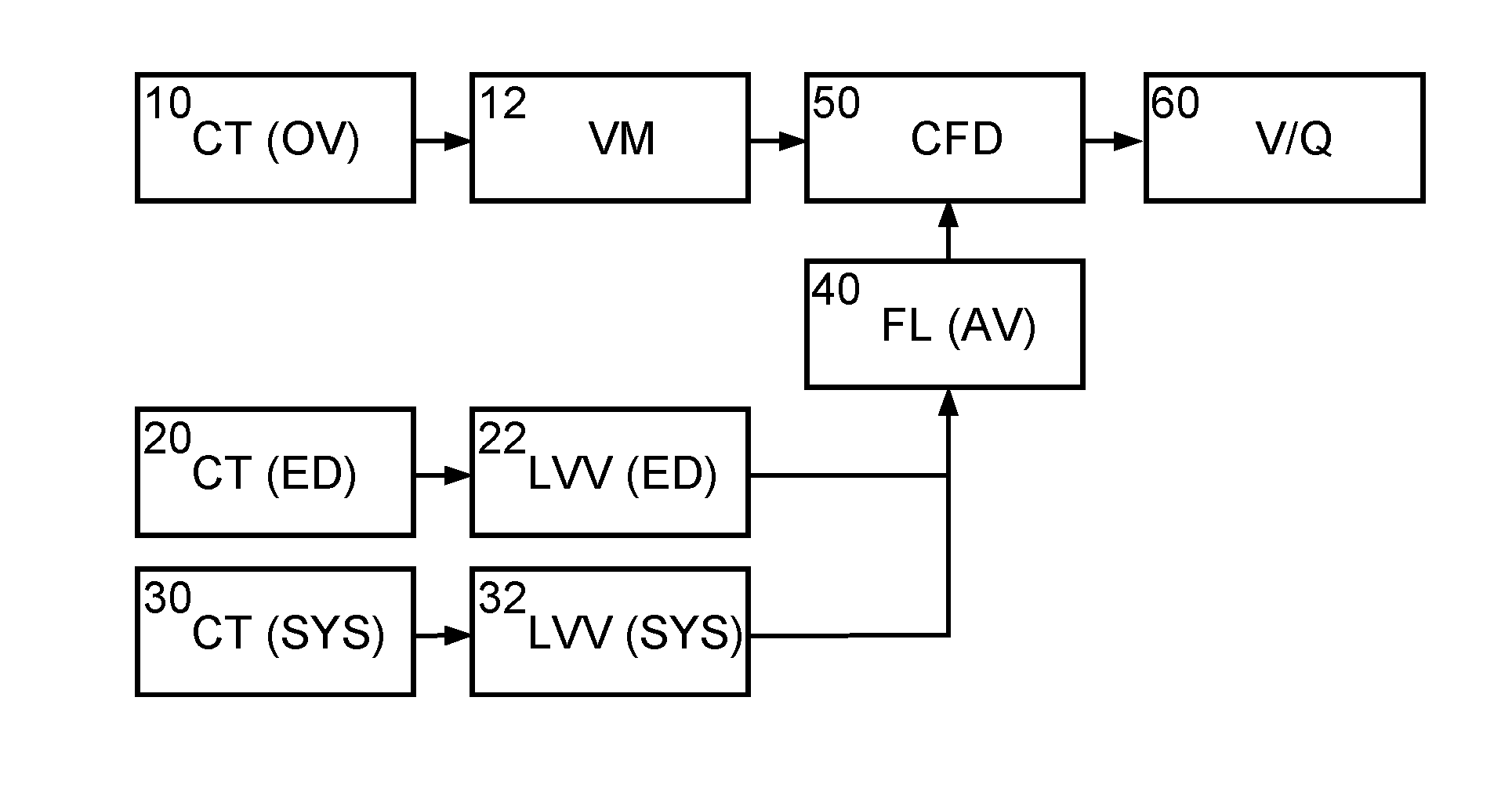
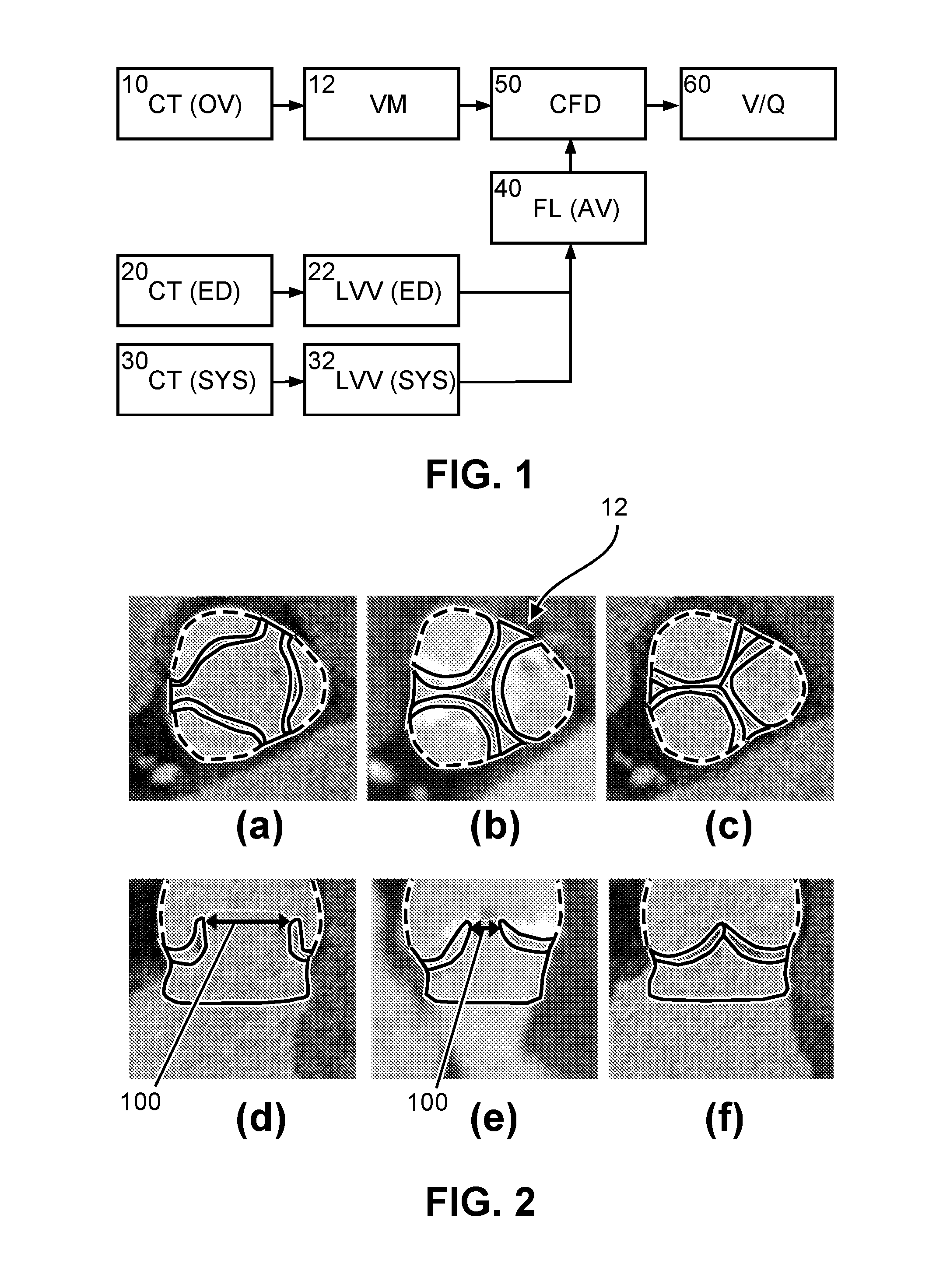
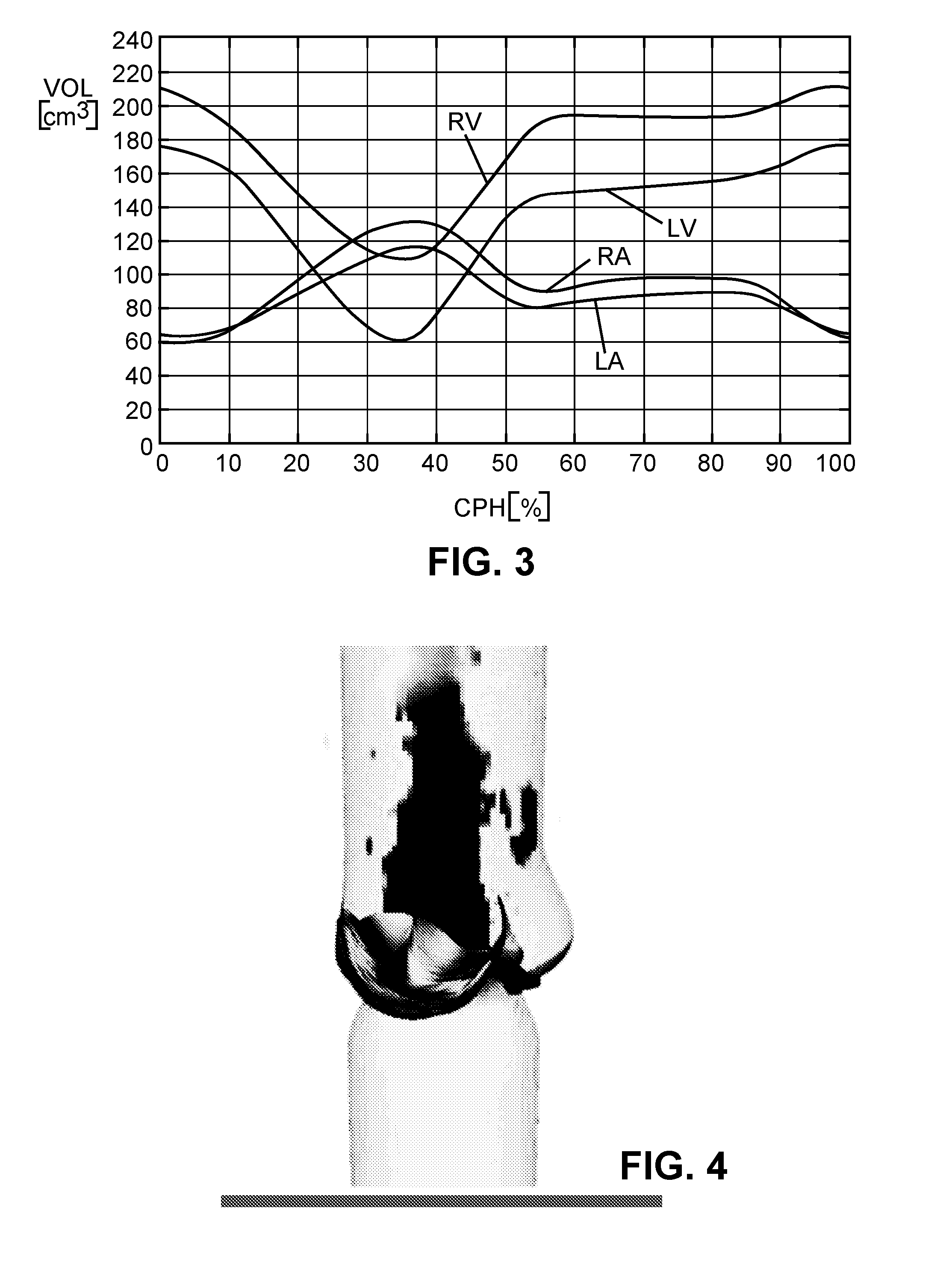
[0020]Embodiments are now described based on a simulation of the blood flow through a patient-specific geometry of a left ventricle (LV) outflow tract plus ascending aorta (as an example for a blood cavity or cardiovascular structure close to the heart) under patient-specific boundary conditions derived from the cardiac ejection output per heart stroke, which blood volume can be calculated from (at least) two images of the LV in maximum and minimum filling state (e.g., end of diastole, end of systole). The geometry of the LV outflow tract, the aortic root including the AV, plus ascending aorta and the ventricle volumes can automatically be obtained by model-based segmentation.

[0021]FIG. 1 shows a schematic block diagram illustrating the generation and use of patient-specific boundary conditions for simulating the flow through the aortic valve. The blocks of FIG. 1 can be regarded as hardware circuits adapted to perform the respective function or as steps of a corresponding method or...


PUM


Abstract

The present invention relates to a method and apparatus for simulating blood flow through a cardiovascular structure, e.g. a blood cavity such as the left ventricle outflow tract, the aortic root including the AV, plus ascending aorta, a ventricle volume, the aorta or any other cavity where blood flows through, under patient-specific boundary conditions derived from the cardiac ejection output per heart stroke. The cardiac ejection output can be estimated from volumes of a heart chamber of the patient in different filling states at two or more different points in time. The results of the flow simulation can be used to derive at least one physiological parameter or can be visualized and virtual Doppler ultrasound images may be generated to allow a physician assessing the result.

Description

FIELD OF THE INVENTION[0001]The invention relates to the field of simulation of blood flow through a target cardiovascular structure, such as—but not limited to—a patient-specific geometry of the left ventricular outflow tract, the aortic root including the aortic valve (AV) and the ascending aorta, based on information acquired through medical imaging techniques.BACKGROUND OF THE INVENTION[0002]Degenerative aortic valve stenosis (AS) is the second most common cardiovascular disease with an incidence of 2-7% in the Western European and North American populations aged beyond 65 years, as described in G. M. Feuchtner, W. Dichtl, et al. “Multislice Computed Tomography for Detection of Patients With Aortic Valve Stenosis and Quantification of Severity”, Journal of the American College of Cardiology 2006, 47 (7), 1410-1417.[0003]Management of patients with degenerative AS depends on the severity of the disease. Assessment of the severity of the stenosis of an aortic valve (AV) can involv...

Claims


Application Information

Patent Timeline
Patent Type & Authority Applications(United States)
IPC IPC(8): G06F19/12A61B5/00A61B8/06A61B5/026A61B6/03G16B5/00
CPCG06F19/12A61B5/0263A61B5/7285A61B8/06A61B6/032G06T19/00G06T2210/41A61B6/503A61B6/5217A61B8/065A61B8/5223A61B5/029A61B5/055G16H50/50G16B5/00
Inventor PETERS, JOCHENWEESE, JUERGENSCHMITT, HOLGER
Owner KONINKLJIJKE PHILIPS NV
Why Eureka
Try Eureka