Catheters with lubricious linings and methods for making and using them

a technology of lubricating linings and catheters, which is applied in the field of catheters, sheaths, and other tubular devices with lubricating linings and coverings, can solve the problems of high undesirable air ingress, difficult to complete the construction of such a catheter, and other modifications of the inner surface to facilitate bonding, etc., to achieve the effect of enhancing the air being evacuated and reducing the bond angle of the inner surfa

Active Publication Date: 2015-11-12
CLPH
View PDF28 Cites 45 Cited by
  • Summary
  • Abstract
  • Description
  • Claims
  • Application Information

AI Technical Summary

Benefits of technology

[0015]For example, the tubular device may include an inner liner defining the inner surface that is formed from a hydrophobic material, such as silicone, HDPE, or a fluoropolymer, having a relatively larger bond angle, which may otherwise attract air bubbles sticking to the inner surface. The coating may include a water soluble material, e.g., a biocompatible salt and / or a surfactant, that bonds to the inner surface and thereby effectively reducing the bond angle of the inner surface.
[0016]Thereafter, the lumen may be flushed, e.g., with saline or other conventional fluids to remove air from the lumen. The coating may resist air within the lumen sticking to the inner surface and enhance the air being evacuated from the tubular device before the device is introduced into a patient's body. The coating may be at least partially removed from the inner surface during the flushing.

Problems solved by technology

In most instances, especially within a patient's arterial system, and most especially in the chambers of the heart, ingress of air is highly undesirable since such bubbles may cause stroke or infarct of tissue, including cardiac tissue.
Constructing such a catheter, however, is complicated because of the difficulty bonding the inner core to the outer portions of the catheter.
Further, because of the inaccessibility of the inner surface of the lumen of a catheter, mechanical abrasion or modification, cleaning, etching, application of adhesive, or other modifications of the inner surfaces to facilitate bonding are generally difficult to complete.
Furthermore, materials such as PTFE may degrade under commonly used sterilization techniques, such as gamma sterilization, and therefore may be inappropriate for certain catheter devices.
PE, similar to PTFE, is also difficult to bond to other materials.
In both cases, the manufacturing process is complicated and the materials generally expensive.
Other methods for imparting lubricity to inner surfaces have been tried, for example, vapor deposition of surface coatings such as Parylene; however, this process is also complicated and does not result in optimal lubricity.
However, application of these and other coatings to inner surfaces is currently significantly hindered by technical challenges and therefore not widely practiced.
However, there may be substantial risk that such air bubbles are subsequently displaced mechanically, i.e., when secondary devices are passed through the lumens.
For example, in the case of a dilator, many bubbles may be removed during dilator insertion (frequently done outside the body), however there is substantial risk that some may remain within the lumen.

Method used


Image

  • Catheters with lubricious linings and methods for making and using them
  • Catheters with lubricious linings and methods for making and using them
  • Catheters with lubricious linings and methods for making and using them

Examples


Embodiment Construction

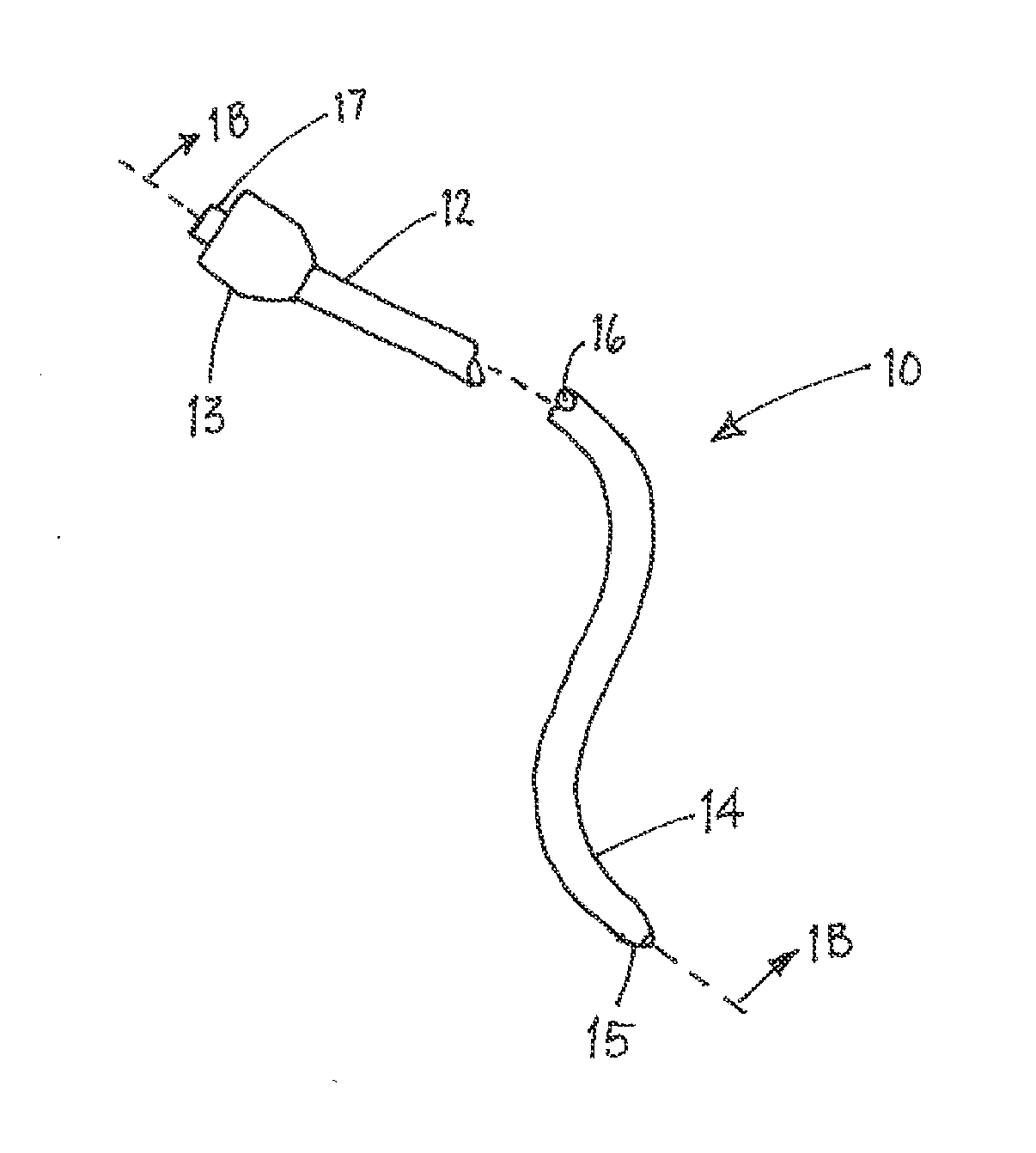
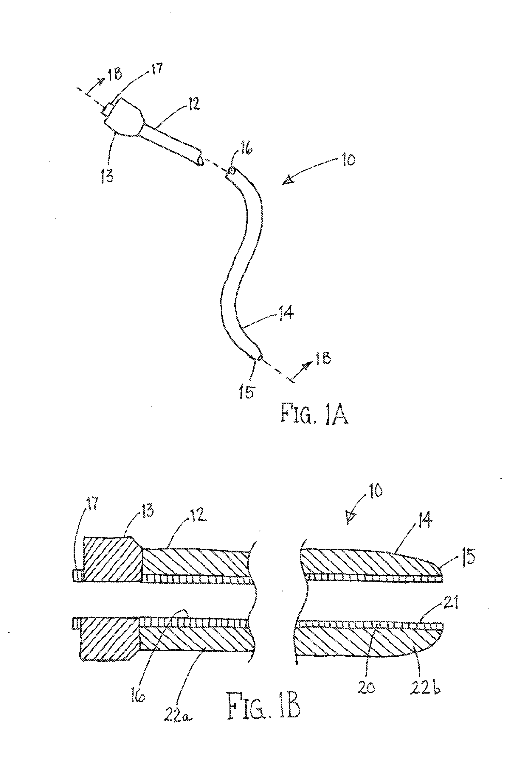
[0065]Turning to the drawings, FIGS. 1A and 1B show an exemplary embodiment of an apparatus 10 for accessing a body lumen (not shown) and / or for delivering one or more fluids, agents, and / or instruments (also not shown) within a body lumen. In exemplary embodiments, the apparatus 10 may be a guide catheter, a procedure catheter, a sheath, an imaging device, or other tubular device sized for introduction into a body lumen, such as a vessel within a patient's vasculature, a passage within a patient's gastrointestinal tract, urogenital tract, reproductive tract, respiratory tract, lymphatic system, and the like, as described further below.

[0066]Generally, the apparatus 10 is an elongate tubular member including a proximal end 12, a distal end 14 sized for insertion into a body lumen, and a lumen 16 extending between the proximal and distal ends 12, 14. Optionally, the apparatus 10 may include one or more additional lumens (not shown), which may be disposed concentrically around or side...


PUM

PropertyMeasurementUnit
bond angleaaaaaaaaaa
lengthaaaaaaaaaa
lengthaaaaaaaaaa

Abstract

Apparatus and methods are provided for creating tubular devices, e.g., as components for catheters, sheaths, and or other devices sized for introduction into a patient. In one embodiment, a method is provided for making a tubular device using a sheet of material including a coated first surface. The sheet is rolled around a mandrel until longitudinal edges of the sheet are disposed near or adjacent one another, e.g., without attaching the longitudinal edges together. A tubular braid is positioned over the sheet-wrapped mandrel, one or more tubular segments are positioned over the tubular braid, and heat shrink tubing is positioned over the tubular segments. The resulting assembly is heated to cause the tubular segments to at least partially reflow and/or otherwise laminate the tubular segments to the tubular braid and sheet. The heat shrink tubing and mandrel are then removed to create the tubular device.

Description

RELATED APPLICATION DATA[0001]This application claims benefit of co-pending provisional application Ser. No. 62 / 000,541, filed May 20, 2014, and is a continuation-in-part of co-pending application Ser. No. 13 / 097,051, filed Apr. 28, 2011, which claims benefit of provisional application Ser. No. 61 / 328,756, filed Apr. 28, 2010 and provisional application Ser. No. 61 / 328,888, filed Apr. 28, 2010, the entire disclosures of which are expressly incorporated herein by reference.FIELD OF THE INVENTION[0002]The present invention relates generally to devices for providing access into body lumens and, more particularly, to catheters, sheaths, and other tubular devices with lubricious linings and coverings and methods for making and using them.BACKGROUND[0003]Catheters are elongate tubular devices sized for introduction into body passages and cavities of a patient, such as a patient's vascular system, gastrointestinal system, abdominal cavity, and the like. A catheter may include one or more l...

Claims


Application Information

Patent Timeline
Patent Type & Authority Applications(United States)
IPC IPC(8): A61M25/00A61N1/05C08J7/043C08J7/056
CPCA61M25/0045A61M25/0009A61M25/005A61M25/0012A61M2207/00A61N1/056A61M2025/0046A61M2025/0062A61M2205/0238A61M25/0053B29L2031/753B29L2031/602A61L29/085A61L29/14B29C65/08B29C65/18B29C65/48B29C65/4835B29C65/4845B29C65/4895B29C65/68B29C65/7435B29C65/7439B29C66/112B29C66/1122B29C66/1142B29C66/135B29D23/001B29C66/344B29C66/432B29C66/4322B29C66/438B29C66/52272B29C66/63B29C66/81423B29L2031/7542B29C66/83413B29C66/84121B32B27/08B29C67/0018B32B27/12B32B27/40B29C69/001B29C53/40B29C53/42B29C53/46B29C61/006B29C65/02B32B1/08A61L2400/10A61M2025/0047A61M2025/0048A61M2025/006B29C2793/0081B29C2793/009B29C48/08B29C48/09B29C48/10B29C48/11B29C48/12B29C48/001B29C48/0018B29C48/0021B29C48/0022B29C48/151B29C48/21C08J7/0427C08J7/056C08J7/043C08L77/00C08L75/04
Inventor LEEFLANG, STEPHEN A.EVERSULL, CHRISTIAN S.
Owner CLPH
Why Eureka
Try Eureka