Minimum on-time control for low load dc/dc converter

a technology of dc/dc converter and dc converter, which is applied in the direction of electric variable regulation, process and machine control, instruments, etc., can solve the problems of poor efficiency, low dc/dc converters that are not generally chosen for low-load converters, and stability problems requiring conventional complex compensation techniques, so as to reduce dc errors, reduce stability problems, and reduce the effect of dc errors

Active Publication Date: 2015-11-12
TEXAS INSTR INC
View PDF7 Cites 27 Cited by
  • Summary
  • Abstract
  • Description
  • Claims
  • Application Information

AI Technical Summary

Benefits of technology

[0030]What is needed is a simpler low load DC/DC converter design that mitigates the stability issues described above but that does not require the additional circuitry needed to implement conventional stabilization techniques such as ERG or the additional circuitry then needed to reduce the DC errors caused by the stabilization technique.
[0031]The present invention provides a system and methods for the...

Problems solved by technology

This type of DC/DC converter however is not generally chosen for low-load converters due to poor efficiency at low loads and since other, simpler designs are available.
However, both the COT type and dual threshold type DC/DC converter, while versatile for low load applications can have stability problems requiring conventional complex compensation techniques.
Under certain conditions and without additional circuitry, COT DC/DC converters can enter states where they become unstable such that a consistent output from cycle to cycle within the desired voltage range cannot be maintained.
However, when used in such circuits as described above, the very low ESR of ceramic capacitors and resulting low ripple le...

Method used


Image

  • Minimum on-time control for low load dc/dc converter
  • Minimum on-time control for low load dc/dc converter
  • Minimum on-time control for low load dc/dc converter

Examples


Embodiment Construction

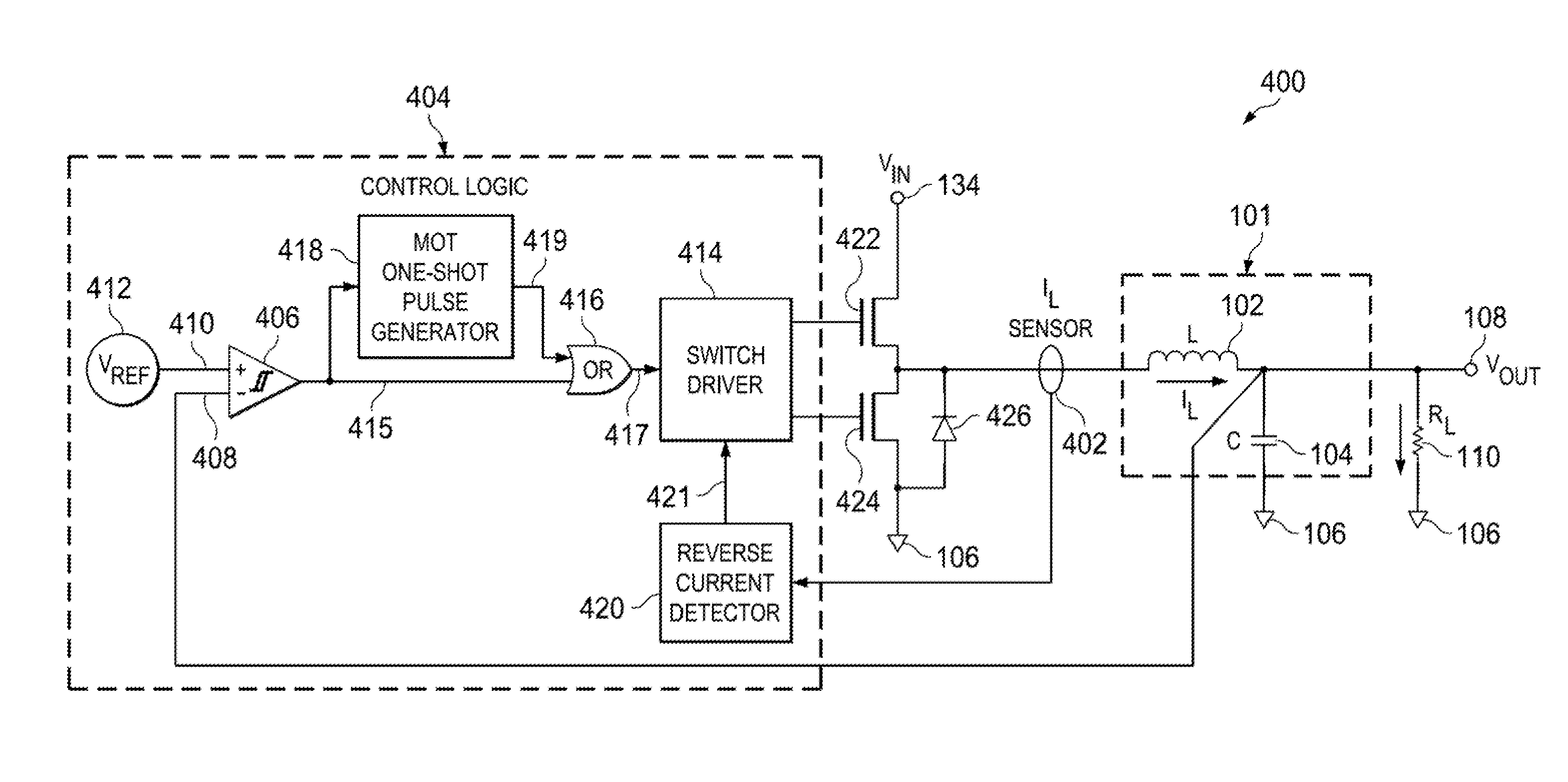
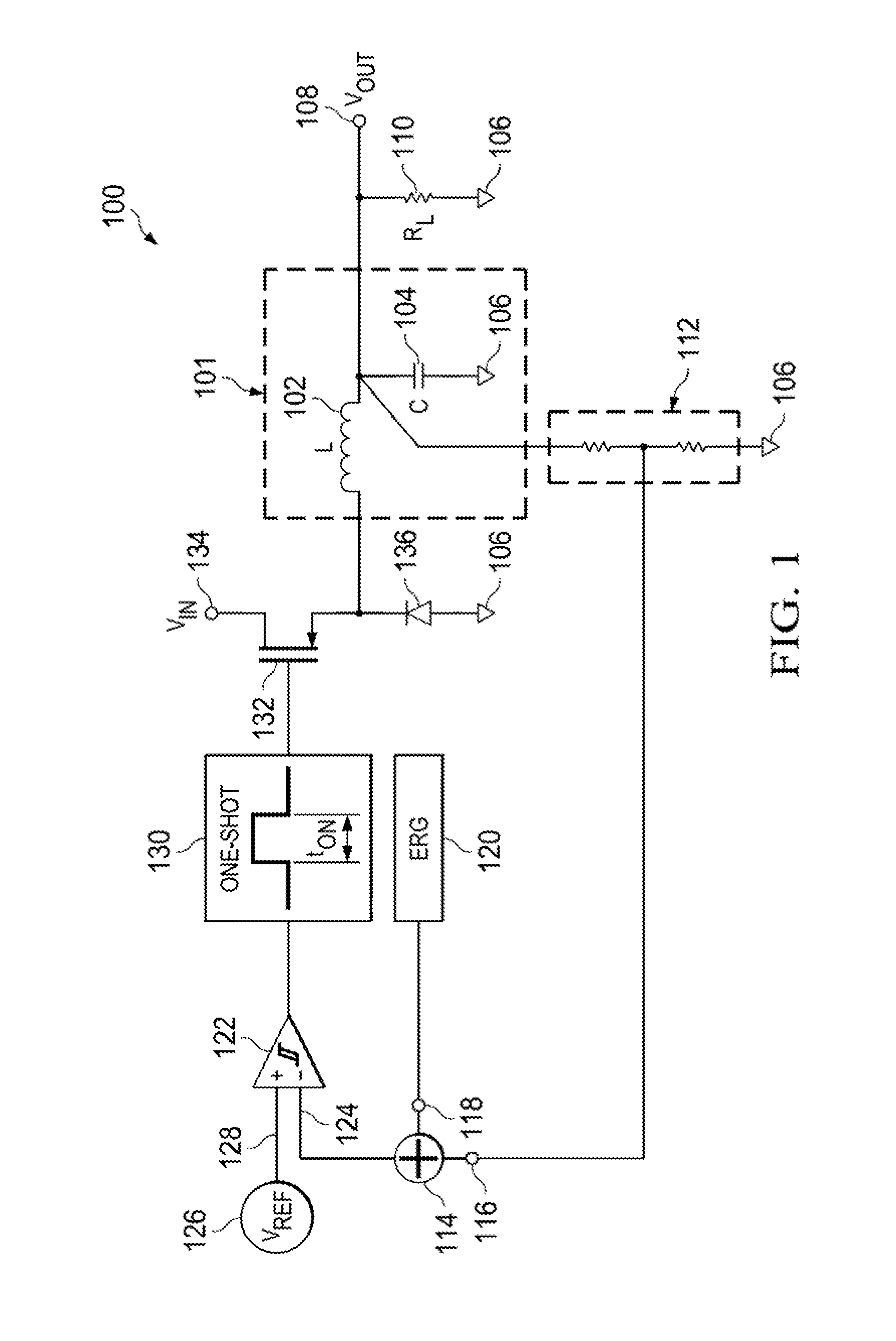
[0042]Aspects of the present invention are drawn to a DC / DC converter for use with a supply voltage, and that may drive a load.

[0043]A first aspect of the present invention is drawn to the use of both leading and trailing edges of an output of a comparator to cause the switching and selection of filter charge and discharge paths for the regulation of the output voltage. Both edges of the comparator are used in a way that imposes a fixed relationship between inductor current and load current in order to ensure scalability of load and output ripple as load decreases. This scalability is a great improvement over conventional low-load DC / DC converters where the output ripple stays high as the load decreases.

[0044]A second aspect of the present invention is drawn to the use of a reverse current detector to determine the point in the regulation cycle to cause the switching and selection of filter charge and discharge paths to force the low-load DC / DC converter operation into Discontinuous...


PUM


Abstract

Aspects of the present invention provide a DC/DC converter for use with a supply voltage and operable to drive a load, wherein the DC/DC converter includes a VIN node, a VOUT node, a switching component, a filter, a comparator, a current detecting component and a control component. The VIN node can receive the supply voltage and the VOUT node can provide an output voltage to drive the load. The filter electrically connects the switching component with the VOUT node. The comparator can generate a comparison signal based on the output voltage. The current detecting component can detect when a current in a direction from the filter toward the VOUT node decreases to zero. The control component can control the switching component so as to provide the output voltage at the VOUT node in a discontinuous conduction mode to drive the load.

Description

BACKGROUND[0001]The present invention generally relates to a switching control method for DC / DC converters.[0002]DC / DC converters are used in many applications but are especially important in portable electronic devices such as cellular phones, tablets and laptop computers which are supplied with power from batteries primarily. A DC / DC converter conventionally uses switching of a DC input voltage to produce a lower DC output voltage to drive its load, and uses a feedback loop to adjust the switching parameters in order to keep the output voltage in a region around a selected average voltage. A common conventional DC / DC converter uses a sawtooth waveform and comparator for pulse width modulation (PWM) in the feedback loop to control the average voltage by keeping the frequency of the pulses constant while adjusting the pulse width. This type of DC / DC converter however is not generally chosen for low-load converters due to poor efficiency at low loads and since other, simpler designs ...

Claims


Application Information

Patent Timeline
IPC IPC(8): H02M1/00H02M1/14H02M3/158
CPCH02M1/00H02M3/158H02M2001/0012H02M2001/0009H02M1/143H02M1/15H02M3/1588Y02B70/10H02M1/0003H02M1/0009H02M1/0012
Inventor RADHAKRISHNAN, MADHANAGARWAL, NITIN
Owner TEXAS INSTR INC
Why Eureka
Try Eureka