Wavelength beam combining laser systems with micro-optics

a laser system and laser technology, applied in lasers, semiconductor lasers, instruments, etc., can solve the problems of difficult to achieve the desired beam quality factor of the final combined beam and/or maintain a relatively small overall footprint of the laser system, and achieve high brightness and high power

a laser system and laser technology, applied in lasers, semiconductor lasers, instruments, etc., can solve the problems of difficult to achieve the desired beam quality factor of the final combined beam and/or maintain a relatively small overall footprint of the laser system, and achieve high brightness and high power

US20150331245A1Active Publication Date: 2015-11-19PANASONIC OF NORTH AMERICA

Image

  • Wavelength beam combining laser systems with micro-optics
  • Wavelength beam combining laser systems with micro-optics
  • Wavelength beam combining laser systems with micro-optics

Examples


Embodiment Construction

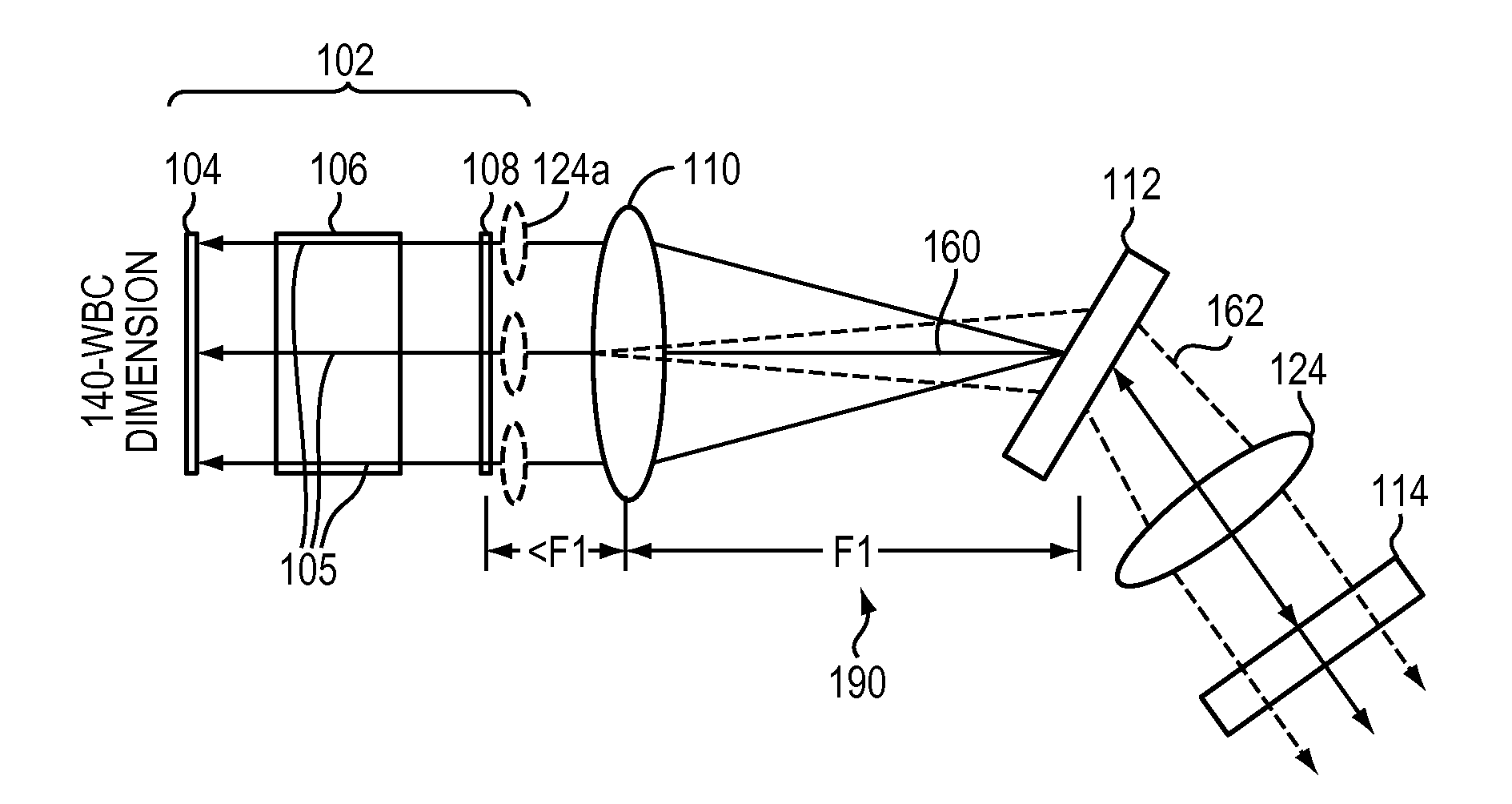
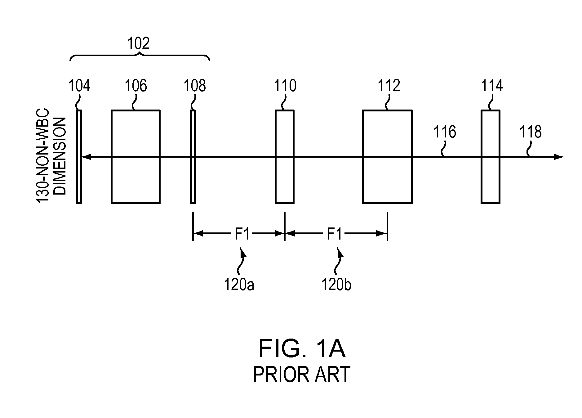
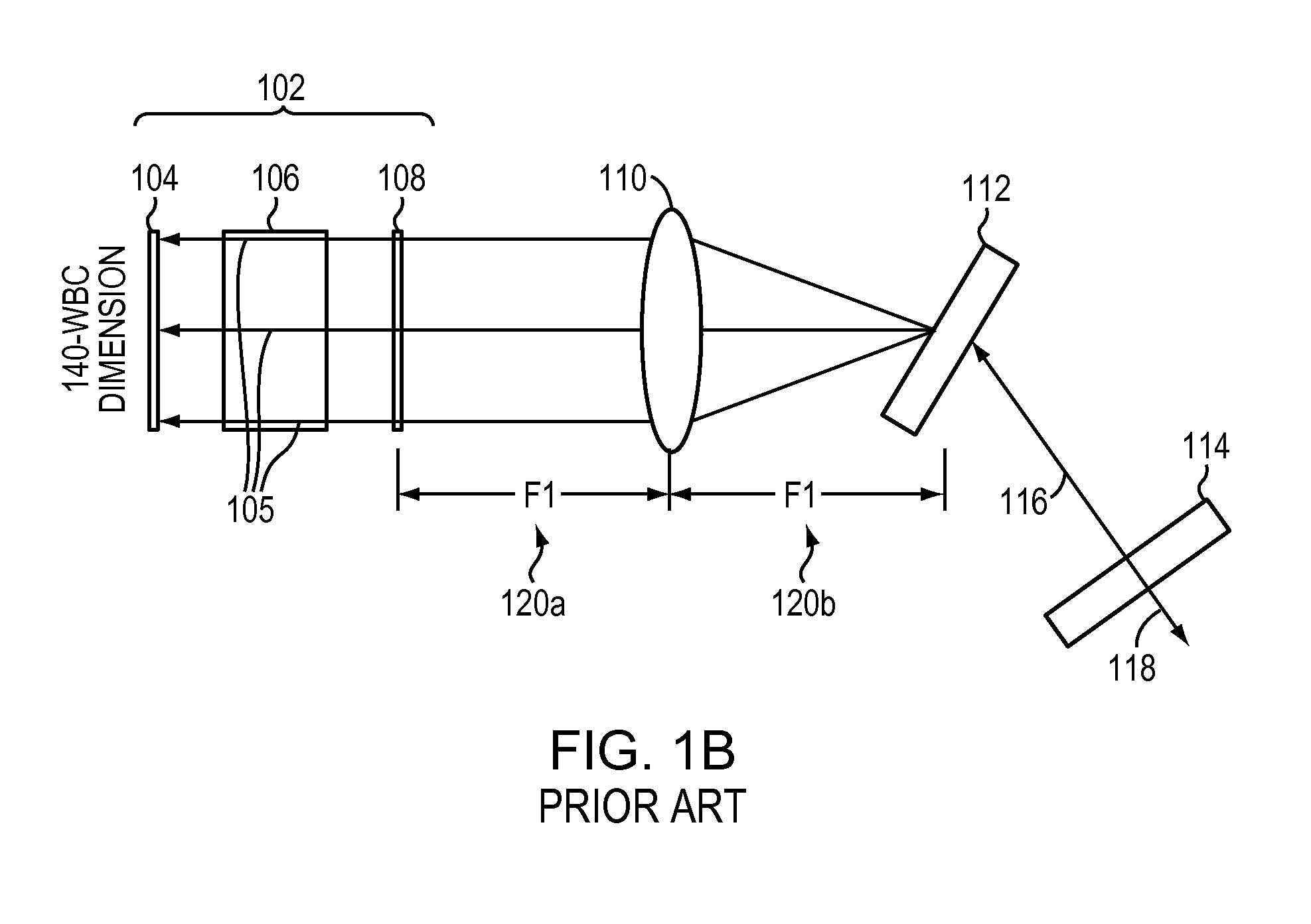
[0034]FIGS. 1A and 1B illustrate a conventional external-cavity one-dimensional wavelength beam combining (WBC) laser system along a non-beam-combining dimension 130 (FIG. 1A) and along a beam-combining dimension 140 (FIG. 1B). As shown, such systems may include a one-dimensional diode bar 102 having a back reflective surface 104, a gain medium 106 with two or more diode emitters 105, a front reflective surface 108, a combining optic (or “focusing lens”) 110, a dispersive element 112, and a partially reflecting output coupler 114. The combining optic 110 is typically placed an optical distance 120a away from the front reflective surface 108 of the diode bar 102, while the dispersive element 112 is placed an optical distance 120b away from combining optic 110, where both optical distances 120a, 120b are substantially equal to the focal length of the combining optic 110. The output coupler 114 is spaced away from the dispersive element 112 and reflects a portion 116 of the generated b...


PUM

PropertyMeasurementUnit
lengthaaaaaaaaaa
lengthaaaaaaaaaa
wavelengthsaaaaaaaaaa

Abstract

In various embodiments, wavelength beam combining systems feature multiple beam emitters each emitting an individual beam, as well as multiple micro-optics arrangements each disposed optically downstream from a beam emitter to intercept the beam emitted thereby and direct the beam toward a dispersive element for combination into a multi-wavelength output beam.

Description

RELATED APPLICATIONS[0001]This application claims the benefit of and priority to U.S. Provisional Patent Application No. 61 / 972,305, filed Mar. 29, 2014, the entire disclosure of which is hereby incorporated herein by reference. This application is also a continuation-in-part of U.S. patent application Ser. No. 13 / 686,974, filed Nov. 28, 2012, which claims the benefit of and priority to U.S. Provisional Patent Application No. 61 / 601,763, filed Feb. 22, 2012, the entire disclosure of each of which is hereby incorporated herein by reference.TECHNICAL FIELD[0002]In various embodiments, the present invention relates to laser systems, specifically wavelength beam combining laser systems with various collimating and converging optics.BACKGROUND[0003]High-power laser systems are utilized for a host of different applications, such as welding, cutting, drilling, and materials processing. Such laser systems typically include a laser emitter, the laser light from which is coupled into an optic...

Claims


Application Information

Patent Timeline
19 Nov 2015
Publication
US20150331245A1
IPC
G02B27/10; G02B5/18
CPC
G02B5/18; G02B27/1006; G02B26/02; G02B27/1086; Y10T29/49895; G02B19/0057; G02B27/4244; H01S5/141
Inventors
TAYEBATI, PARVIZ; CHANN, BIEN