
Laser Differential Confocal Mapping-Spectrum Microscopic Imaging Method and Device

a microscopic imaging and confocal mapping technology, applied in the field of optical microscopic imaging and spectral measurement, can solve the problems of raman spectrum energy reduction, low signal noise ratio of confocal positioning, and large size of actually detected “micro-areas” to be much greater than. , to achieve the effect of improving spatial resolution and high spatial resolution

Active Publication Date: 2015-12-03
BEIJING INSTITUTE OF TECHNOLOGYGY
View PDF4 Cites 24 Cited by
  • Summary
  • Abstract
  • Description
  • Claims
  • Application Information

AI Technical Summary

Benefits of technology

The present invention aims to overcome the difficulty in improving spatial resolution in confocal Raman spectroscopy. The invention provides a laser differential confocal mapping-spectrum microscopic chromatography imaging method and device with high spatial resolution. This is enabled by a method of accurately focus-tracking the measured sample during the measurement process, using the zero-cross point of the differential confocal curve generated by a dichroic beam splitting system. This allows for a reduction in environmental factors such as temperature and vibration that may affect the spectral measurement, resulting in improved accuracy. The excitation beam used in the invention may be a polarized beam or a structural beam generated by the pupil filtering process, which can compress the size of the measuring converging spot to improve lateral resolution.

Problems solved by technology

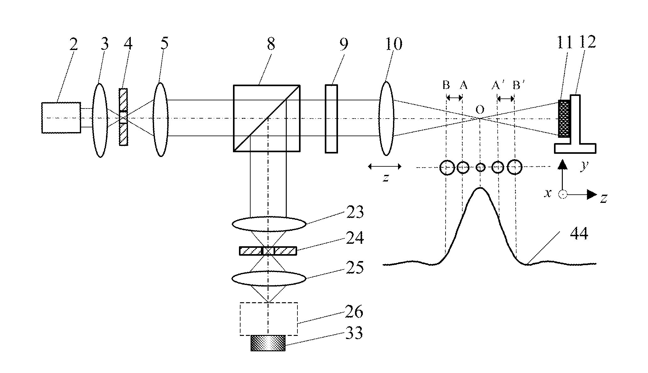
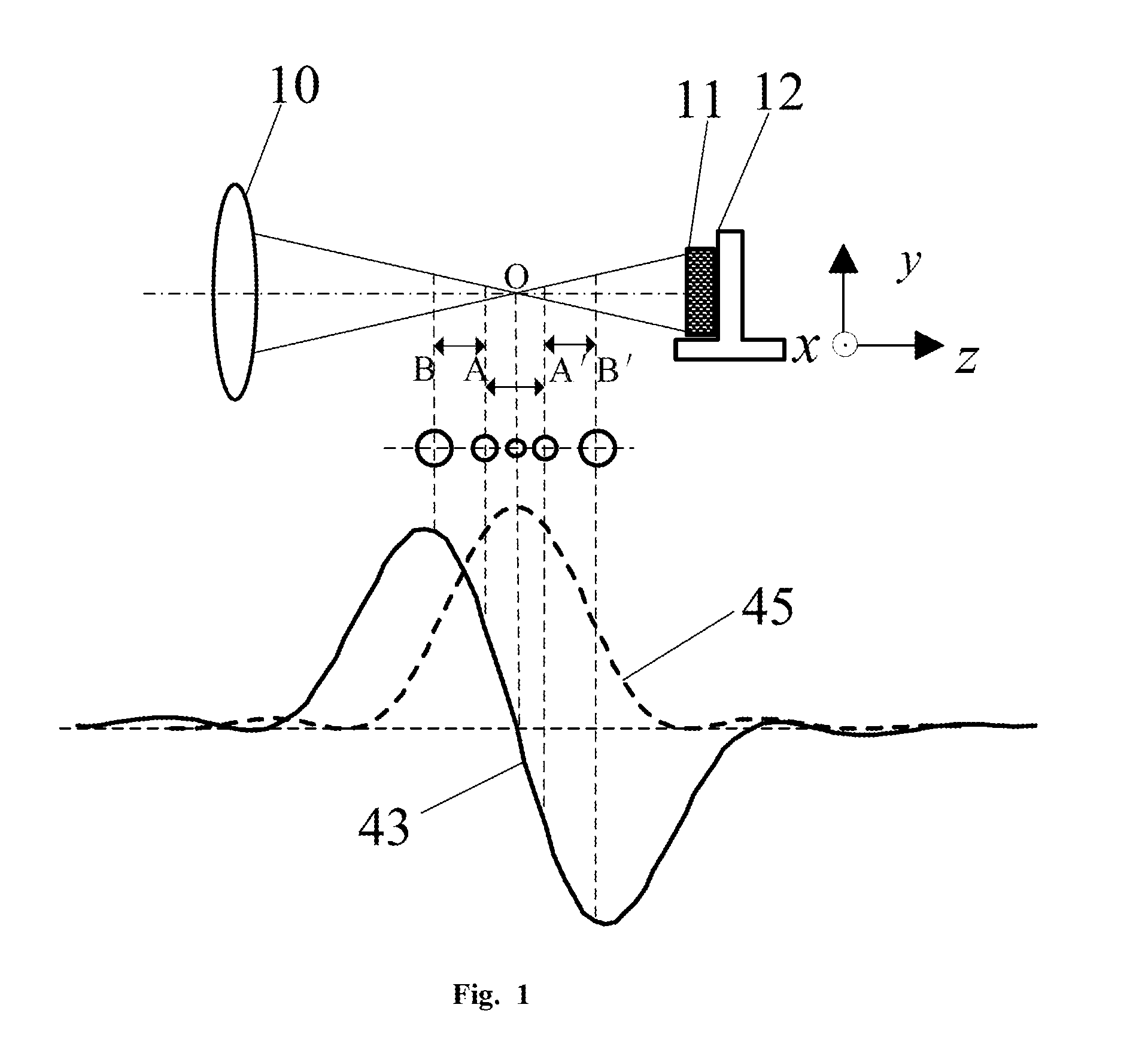
Therefore, the actual detection position of the confocal Raman microscopy is usually placed in out-of-focus BA and A′B′ zones in confocal curve, causing the size of actually detected “micro-area” to be much greater than that of the focus O. Meanwhile, the signal noise ratio of confocal positioning of the utilization of Raman spectrum technology is low.
The energy of the Raman spectrum may be further reduced due to the blocking effect of the pinhole; on the other hand, the expansion of the pinhole size for increasing the passing through rate of the spectrum may increase FWHM (full width at half maximum) of confocal axial intensity curve and reduce its positioning accuracy.
The relatively large size of pinhole also can't act well on focusing.
Above reasons restrict the ability of the confocal Raman microscopy system to detect the micro-area spectrum, constraining its application to a more precise micro-area spectral measurement and analysis area.
While the overall performance of spectrum system could be improved, the spatial resolution of confocal Raman spectroscopy system has not been improved significantly.
Therefore, the improvement of the spatial resolution of Raman spectrum system is still a pending issue.
However, in order to obtain more accurate and more abundant measurement information, the Raman spectral imaging not only performs multiple-point Raman spectrum detection to the sample, but also needs a relative long time Raman spectrum detection to each point of the multiple-point.
As a result, the Raman spectral imaging needs a relative long time for detection.
It often takes a few hours to complete imaging.
However, in the long-time imaging process, the instrument may be significantly influenced by, for example, environment temperature, vibration, air fluctuation, which may easily cause the instrument system to drift, thereby resulting in the out-of-focus of the detected position of the sample; since the existing confocal Raman spectroscopy does not have the ability of a real-time focus-tracking, the out-of-focus error of the sample which is caused by the offset of detected position can not be compensated, thereby restricting the improvement of the spatial resolution of the confocal Raman spectral imaging technology.
However, the existing confocal Raman detection technology could not accurately control the size of the converging spot.

Method used


Image

  • Laser Differential Confocal Mapping-Spectrum  Microscopic Imaging Method and Device
  • Laser Differential Confocal Mapping-Spectrum  Microscopic Imaging Method and Device
  • Laser Differential Confocal Mapping-Spectrum  Microscopic Imaging Method and Device

Examples


Embodiment Construction

[0040]The present invention will be further described with reference to the drawings and embodiments hereinafter.

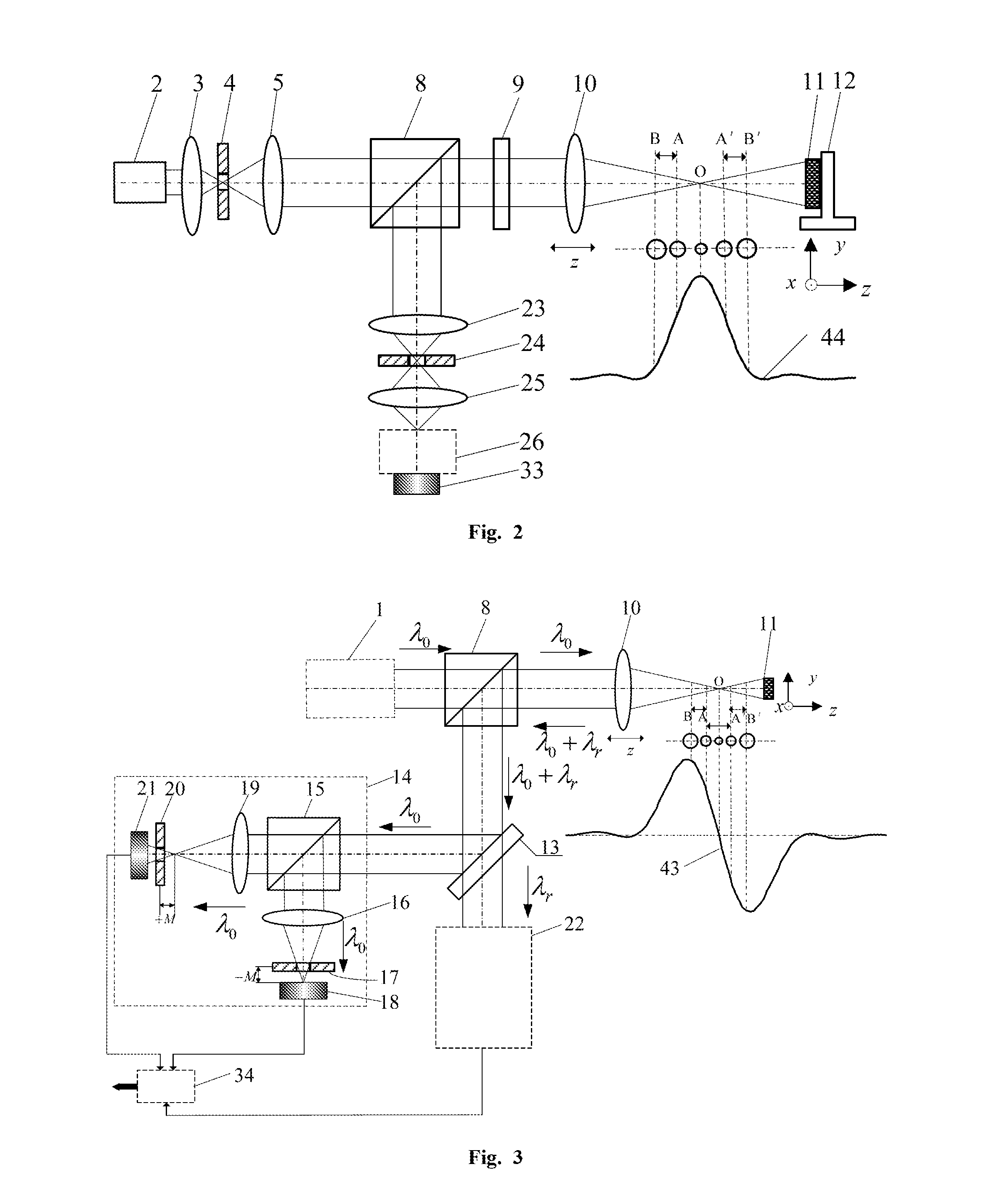
[0041]The main concept of the present invention is to utilize the combination of the differential confocal detection and spectrum detection to achieve a “mapping & spectrum in one” spectrum detection.

[0042]As shown in FIG. 3, after passing through a first beam splitting system 8 and an objective 10, the excitation light generated by an excitation beam generation system 1 may be focused on a measured sample 11 and excited Rayleigh light and Raman scattering light that carries the spectral characteristics of the measured sample 11. The excited Raman scattering light and the Rayleigh light may be recycled into the light path by the system and then be reflected to a dichroic beam splitting system 13 by a first beam splitting system 8 following passing through the objective 10. After being split by the dichroic beam splitting system 13, the Raman scattering light and the Rayle...


PUM


Abstract

The present invention belongs to a technical field of optical microscopic imaging and spectral measurement, and discloses a laser differential confocal mapping-spectrum microscopic imaging method and device. The core concept of the present invention is to combine the differential confocal detection and the spectrum detection techniques and use a dichroic beam splitting system (13) to separate the Rayleigh light for geometric position detection from the Raman scattering light for spectrum detection, by mean of the property that the zero-cross point of the differential confocal curve (43) accurately corresponds to the focus of the objective, the spectral information at focus of the excitation spot being accurately captured by the zero trigger to accomplish the spectrum detection with high spatial resolution. Therefore, the present invention provides a method and device that may be able to accomplish the spectrum detection with high spatial resolution to a micro-area of a sample.

Description

TECHNICAL FIELD[0001]The invention belongs to a technical field of optical microscopic imaging and spectral measurement, and relates to a laser differential confocal mapping-spectrum microscopic imaging method and device, which may be used for three-dimensional morphology reconstitution and micro-area spectrum detection for varied samples.BACKGROUND ART[0002]In 1990, G. J. Puppels et al., reported their invention of laser confocal Raman microscopy technology in the journal Nature, which combined Raman spectrum detection technology and laser confocal microscopy technology, and which was a revolutionary breakthrough in Raman technology. This technology not only came into the high resolution chromatography imaging characteristics of confocal microscopy, but also could perform spectral analysis to samples; which can implement chromatography detection with high resolution for the micro-area spectrum of the sample. These remarkable advantages make the laser confocal Raman microscopy techn...

Claims


Application Information

Patent Timeline
IPC IPC(8): G01N21/65G01N21/47
CPCG01N21/65G01N2201/063G01N21/47G01N21/658
Inventor ZHAO, WEIQIANCUI, HANQIU, LIRONGWANG, YUN
Owner BEIJING INSTITUTE OF TECHNOLOGYGY
Learn More