Fluid cooled integrated photovoltaic module

a photovoltaic module and flue gas technology, applied in the direction of thermal-pv hybrid energy generation, pv power plants, lighting and heating apparatus, etc., can solve the problems avoid differential expansion, creep, sagging, etc., and achieve the effect of reducing mounting penetration, avoiding differential expansion, and constant uniform compression for

Active Publication Date: 2015-12-03
FAFCO INC
View PDF5 Cites 20 Cited by
  • Summary
  • Abstract
  • Description
  • Claims
  • Application Information

AI Technical Summary

Benefits of technology

[0015]The polymer backsheet has a height that is slightly more than the distance between the back of the frame and back of tube sheet when pressed against the back of the photovoltaic module. The backsheet design ensures the polymer heat exchanger maintains uniform and direct contact with the back of the photovoltaic module in order to have effective thermal transfer. The use of thermoset backsheet maintains constant uniform compression force over the product lifetime since the spring forces are well within the elastic limit and not subject to thermal deflection or creep. The backsheet has no rough edges that can abrade the polymer heat exchanger or it has closure or trim pieces to cover any rough edges. When mounted on the rail system, the assembly is tight and the tube sheet is firmly pressed against the back of the photovoltaic module, but not so hard as to damage the backsheet or photovoltaic module. Prior art has sought to achieve a thermal interface between a photovoltaic module and polymer heat exchanger without success due to delamination induced by thermal expansion/contraction by using adhesives in the case of U.S. Pat. No. 6,675,580 B2. The present invention eliminates the need for any secondary interfacing material between the photovoltaic module and heat exchanger. The two are put into direct mechanical contact. The method of nesting the polymer heat exchanger inside the photovoltaic module avoids issues with differential expansion, creep, sagging, binding and general ease of assembly, service and disassembly. The polymer heat exchanger is constrained at the top of the assembly and the tube sheet and bottom manifold are allowed to freely expand and contract within the rigid frame structure. The soft material of the tube sheet eliminates any potential abrasion wear on the back of the photovoltaic module. Some photovoltaic modules have glass backsheets which further mitigates potential abrasion.
[0016]The cooled photovoltaic system includes a typical photovoltaic electrical system along with a typical solar thermal system. Fluid is ...

Problems solved by technology

This further reduces mounting penetrations compared to mounting p...

Method used


Image

  • Fluid cooled integrated photovoltaic module
  • Fluid cooled integrated photovoltaic module
  • Fluid cooled integrated photovoltaic module

Examples


Embodiment Construction

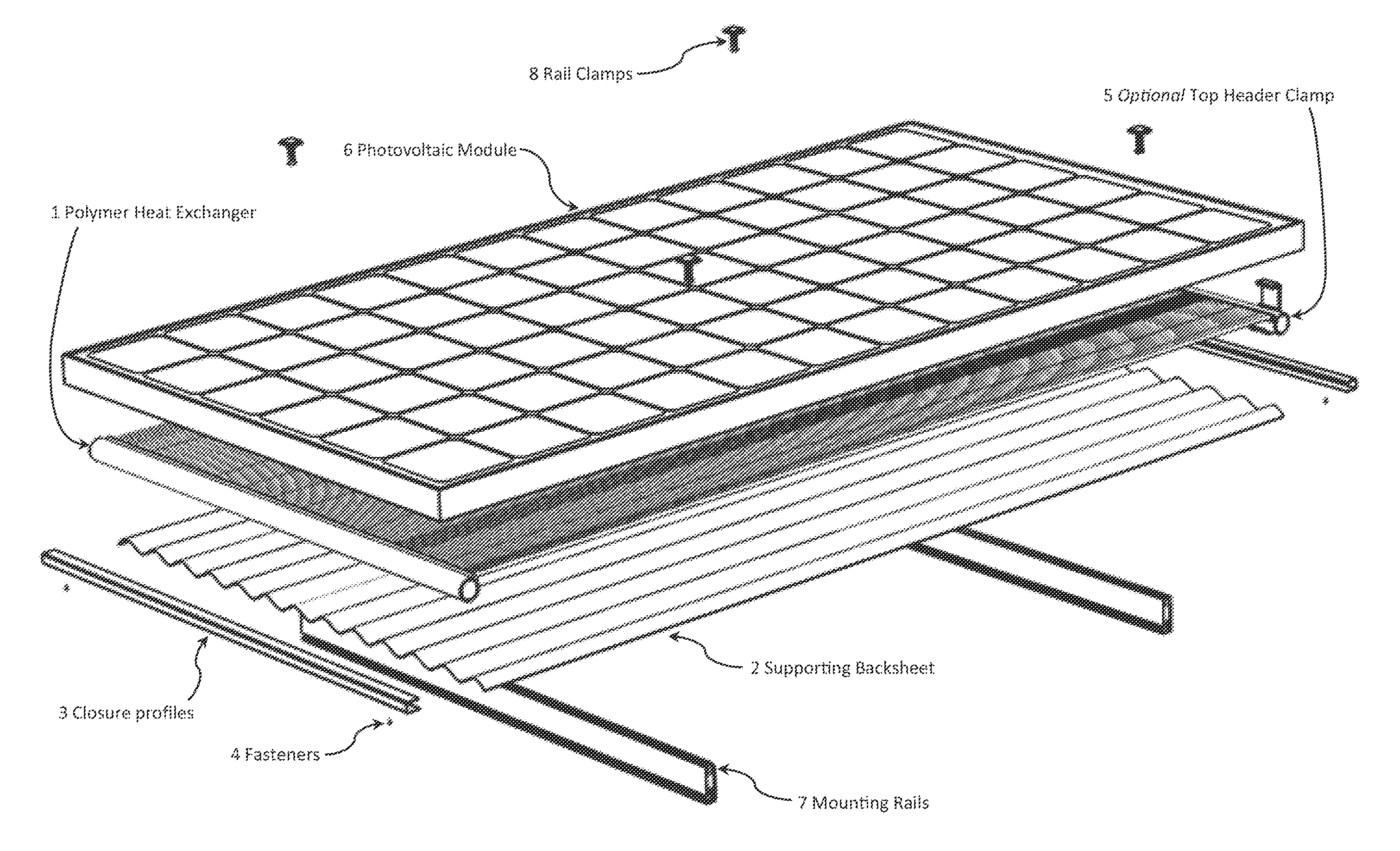
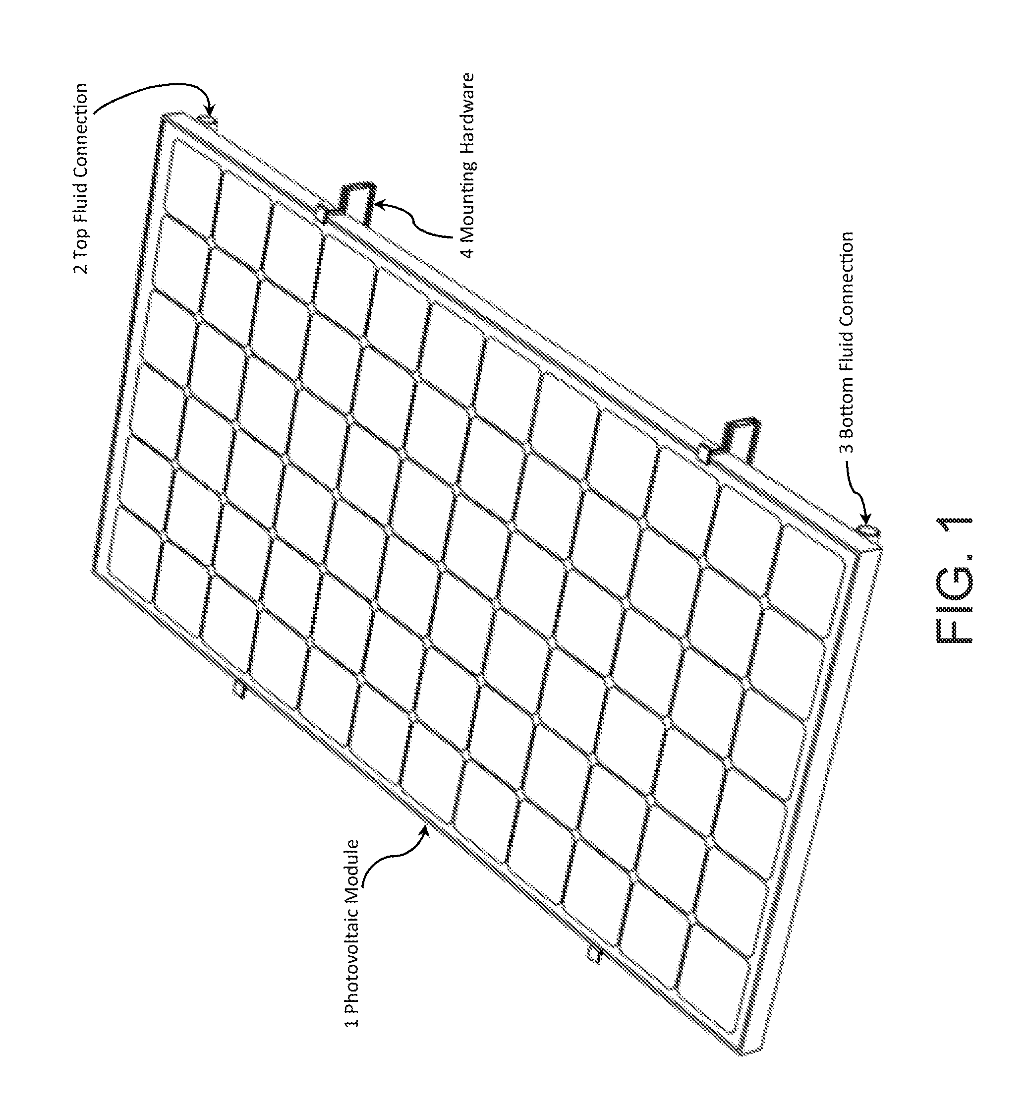
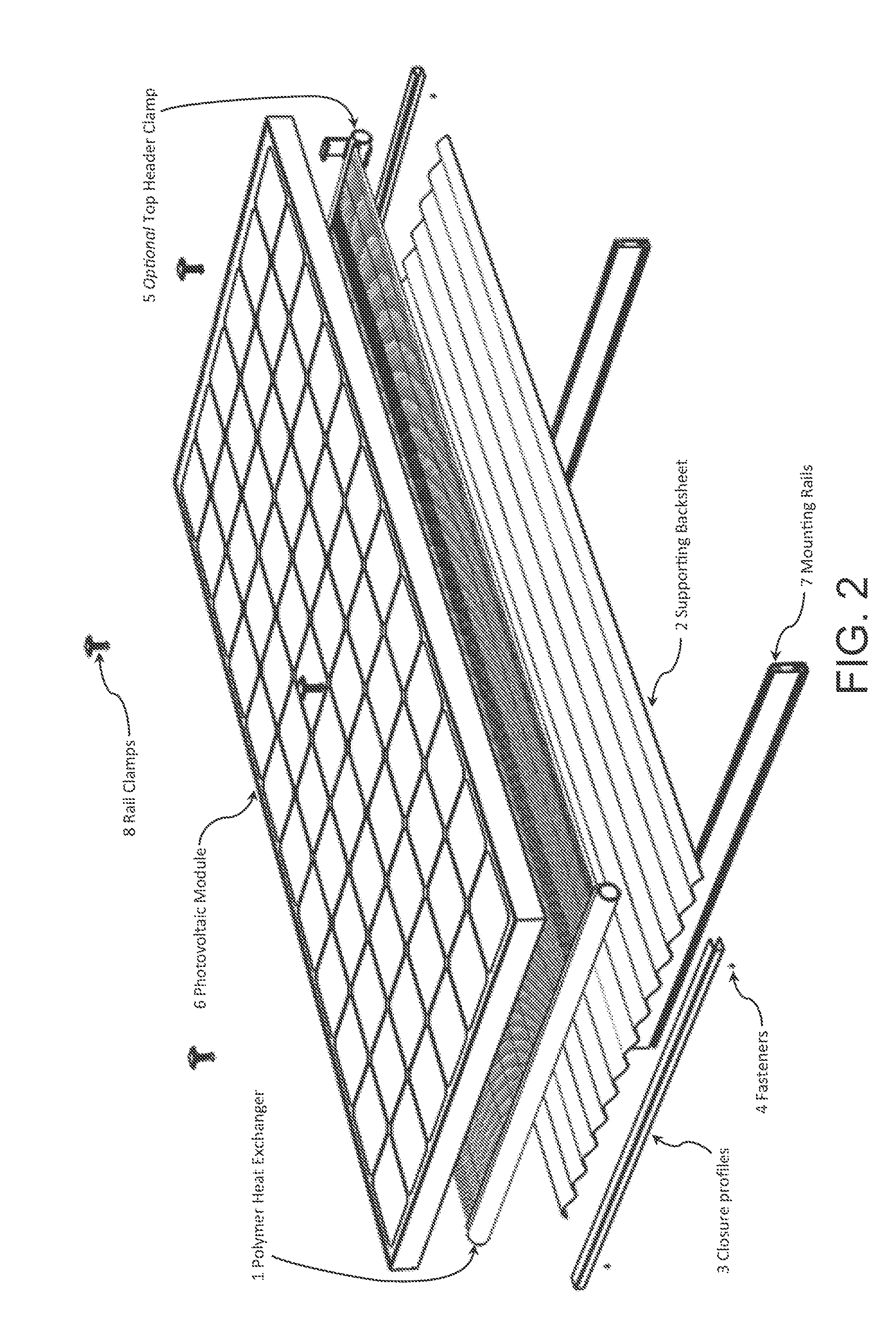
[0037]The present invention relates to photovoltaic devices and applications. More specifically, embodiments of the present invention provide a fluid cooled photovoltaic module assembly and related methods. By combining photovoltaic and solar thermal technologies the energy output can be three to five times greater than that of a photovoltaic module alone, along with numerous other benefits. The present invention describes a successful combination of a photovoltaic module and polymer heat exchanger which yields increased electrical output as well as usable heat, substantially increasing the utilization of available solar energy.

[0038]The following description is presented to enable one of ordinary skill in the art to make and use the invention and to incorporate it in the context of particular applications. Various modifications, as well as a variety of uses in different applications will be readily apparent to those skilled in the art, and the general principles defined herein may ...


PUM

PropertyMeasurementUnit
Angleaaaaaaaaaa
Thicknessaaaaaaaaaa

Abstract

A fluid cooled photovoltaic module in which a polymer heat exchanger transfers heat from the photovoltaic module to a circulated fluid. The photovoltaic module is maintained at a cool temperature enabling increased power output while the heat transferred to the circulated fluid can be useful for applications that require heat. A polymer heat exchanger is specifically utilized to achieve a robust design that is cost effective; high performance; easily adaptable to various photovoltaic module types and sizes; compatible with conventional photovoltaic module balance of systems; light weight; resistant to water sanitizers and other chemicals; resistant to lime-scale buildup and heat exchanger fouling; corrosion resistant; easily transported, assembled, installed, and maintained; and leverages high production manufacturing methods.

Description

CROSS-REFERENCE TO RELATED APPLICATIONS[0001]This application is a Continuation-In-Part application of, and claims priority to, U.S. Nonprovisional patent application Ser. No. 14 / 290,517, filed May 29, 2014, which is related to U.S. Nonprovisional patent application Ser. No. 14 / 201,652, filed Mar. 7, 2014, which claims the benefit of U.S. Provisional Patent Application No. 61 / 778,204, filed Mar. 12, 2013, all of which are commonly assigned and incorporated by reference herein for all purposes.BACKGROUND OF THE INVENTION[0002]The present invention relates to photovoltaic devices and applications. More specifically, embodiments of the present invention provide a fluid cooled photovoltaic module assembly and related methods.[0003]Efficient renewable energy conversion mechanisms are sought to offset worldwide fossil fuel consumption. The International Energy Agency (EA) estimates world energy use in 2010 to be 150 trillion kilowatt-hours, which is roughly 0.02% of annual global solar en...

Claims


Application Information

Patent Timeline
IPC IPC(8): H01L31/052H02S40/42H02S40/44H01L31/024
CPCH01L31/0525H01L31/0521H02S40/44H02S40/425H01L31/024H02S20/00H02S30/10F28F21/062F28F1/00Y02B10/10Y02B10/20Y02B10/70Y02E10/52H01L31/0445H01L31/0547H02S40/42H01L31/052Y02E10/50Y02E10/60
Inventor RUBIO, MICHAEL R.LECKINGER, ROBERTWARD, ALEXANDER P.
Owner FAFCO INC
Why Eureka
Try Eureka