Radio Frequency State Variable Measurement System And Method

a measurement system and frequency state technology, applied in the direction of resistance/reactance/impedence, instruments, measurement devices, etc., can solve the problems of affecting the accuracy of measurement, complex, cumbersome measures to mitigate, and the variability of cavity and waveguide measurement systems, so as to reduce measurement variability, improve measurement accuracy, and reduce measurement response time

Inactive Publication Date: 2015-12-10
FILTER SENSING TECH
View PDF4 Cites 33 Cited by
  • Summary
  • Abstract
  • Description
  • Claims
  • Application Information

AI Technical Summary

Benefits of technology

[0012]A measurement system and method of conducting cavity resonance and waveguide measurements is disclosed. The cavity or waveguide may be used to monitor the amount, composition, or distribution of a material or sample contained in the cavity or waveguide or passing through the cavity or waveguide. Improved means for operating the measurement system to reduce measurement variability, system stability, improve measurement accuracy, and decrease measurement response times are described. The invention's broad applications range from measurements of filters, catalysts, pipe, and ducts where the material collected in or passing through the cavity or waveguide exhibits dielectric properties different from the material which it displaces.

Problems solved by technology

Despite the broad applicability, there are a number of disadvantages of microwave cavity and waveguide measurement systems, which adversely affect the measurement accuracy, or have, heretofore, required complex, costly, and cumbersome measures to mitigate.
First, cavity and waveguide measurement systems typically suffer from part-to-part variability, as small changes in cavity or waveguide geometry (due to manufacturing tolerances, thermal expansion / contraction, assembly variations, and other factors) can affect the microwave resonance response and introduce errors into the measurements.
In addition, changes to material present within the cavity or waveguide, such as filter elements or catalyst substrates, the presence of conducting elements, or the accumulation of material on the walls, may also adversely affect the microwave response of the system.
Changes to the cavity over time, such as the loosening of clamps or other fasteners, of the introduction of certain changes to the cavity geometry, such as dents in one example, may also negatively affect the measurements.
Oftentimes, the dielectric properties of the sample within the cavity may be affected by a number of parameters, which may also introduce errors in the measurement if not properly accounted for.
The impact of these additional parameters, which may be introduced by the measurement method itself or the measurement environment, on the dielectric properties of the sample inside the cavity can, thus, introduce significant errors in the measurements.
Third, the spatial distribution of material inside the cavity or waveguide also affects the measurement sensitivity, based on the specific electric field distribution inside the cavity or waveguide.
Fourth, the implementation of cavity or waveguide measurement systems in process control applications, such as the control of engines, production processes, chemical processing, petroleum extraction, and other applications often requires fast response times for real-time or near real-time feedback control.
Many conventional cavity and waveguide measurement systems exhibit relatively slow response, (slower than 1 Hz) and, thus, have limited utility for applications where fast response measurements are required.
Fifth, in applications where the sample or material inside the cavity or passing through the cavity or waveguide exhibits a high degree of dielectric loss, the microwave signal may saturate rapidly, meaning the amplitude becomes difficult to distinguish from the noise.
Sixth, in certain applications, particularly in cavity or waveguide measurement systems where more than one type of material may be present and have an effect on the resonance response, it may be difficult to monitor the presence of one specific constituent from a mixture of more than one constituent.
In a related application, the constituent's dielectric properties may only be moderately different from the dielectric properties of the media which it displaces in the cavity or the other materials in the mixture, thereby making it difficult to detect (weak sensitivity).
Seventh, the microwave generation and detection systems may not be highly stable, with variations having to do with age, temperature and other environmental characteristics.

Method used


Image

  • Radio Frequency State Variable Measurement System And Method
  • Radio Frequency State Variable Measurement System And Method
  • Radio Frequency State Variable Measurement System And Method

Examples


Embodiment Construction

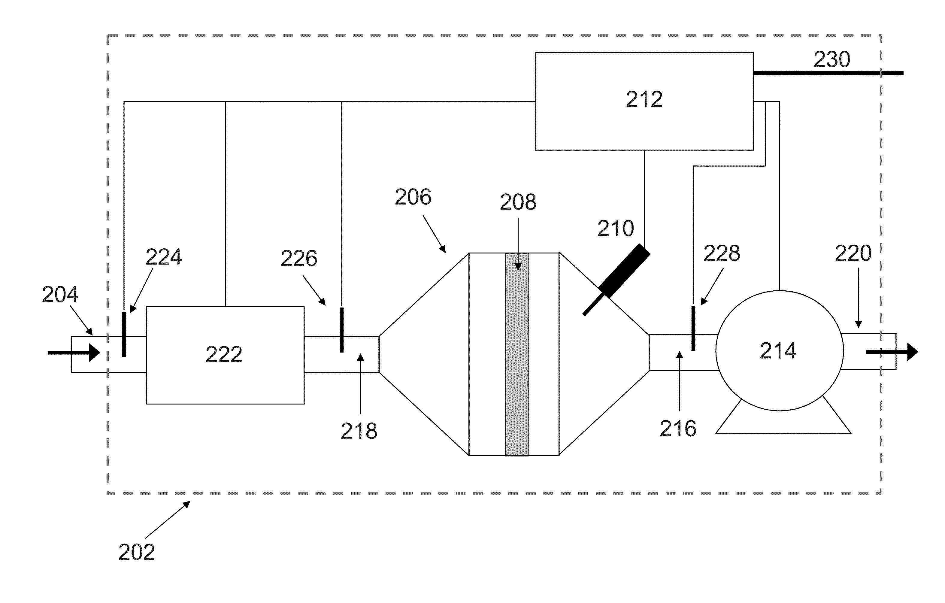
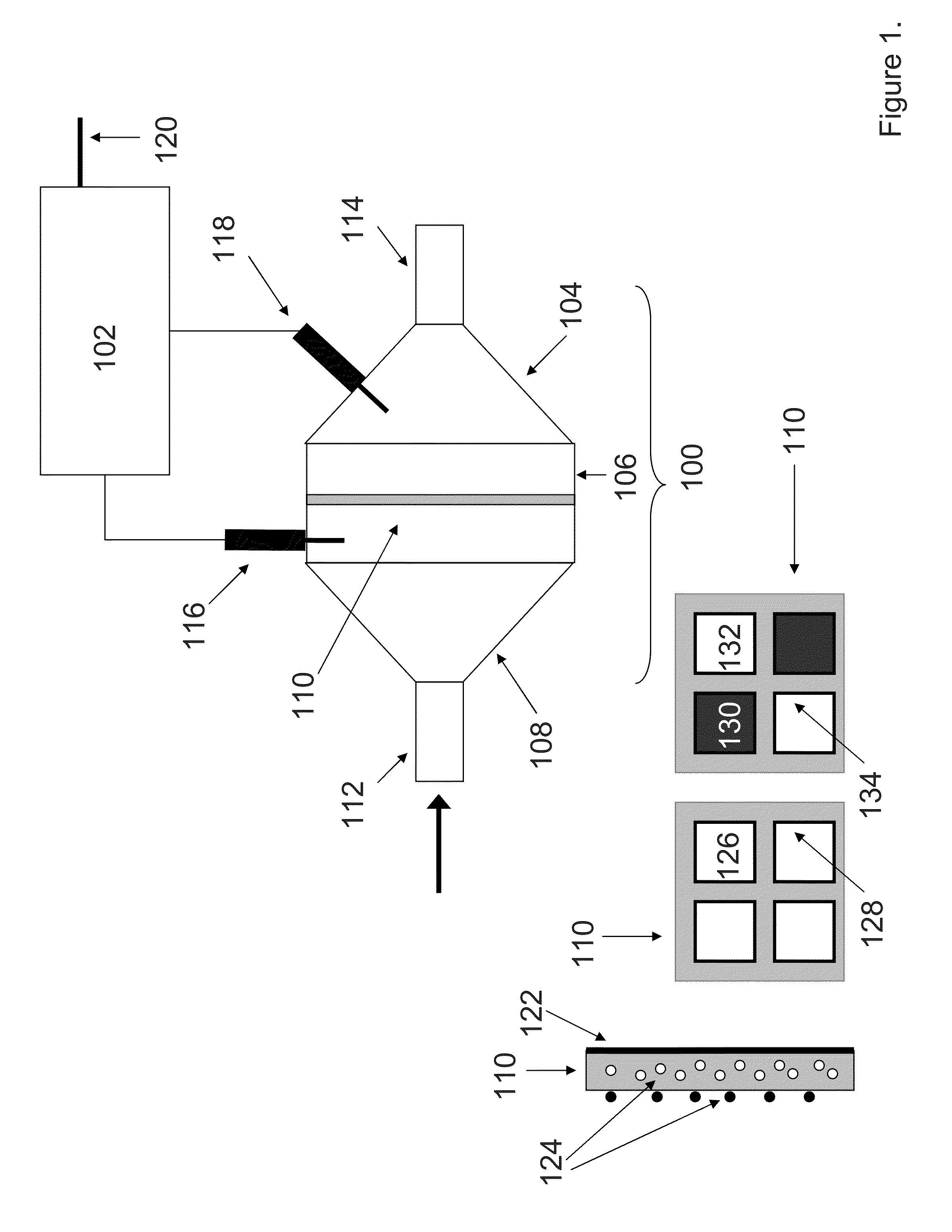
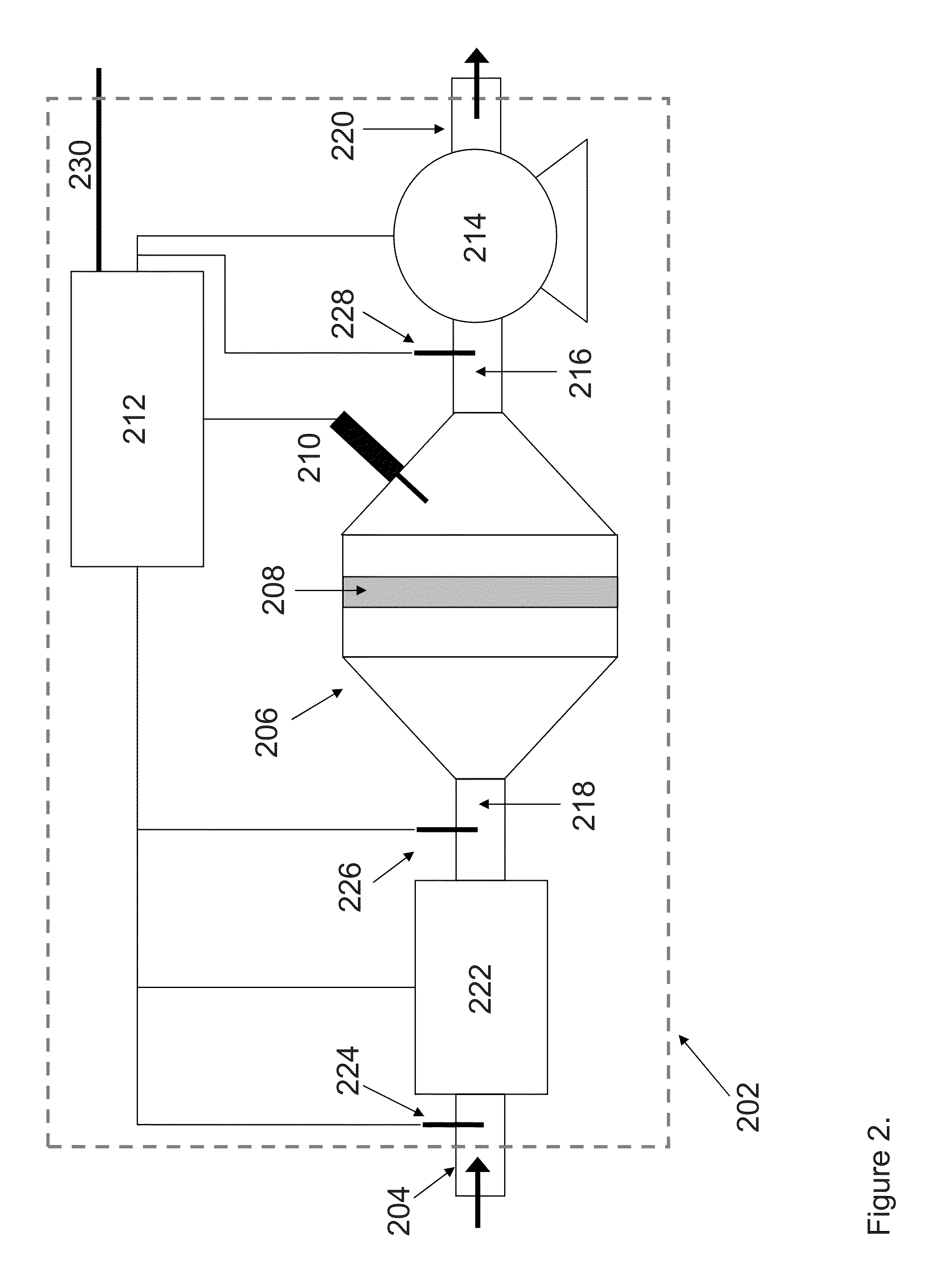
[0038]FIG. 1 depicts a cavity measurement system according to one embodiment. A measurement cavity 100 is made up of a housing 106, which may or may not contain an internal element 110. The internal element 110, if present, may be a filter, membrane, ceramic substrate, catalyst support, or the like. The housing 106 may be connected to conduits 112 or 114, such as pipes, tubes, or ducts to direct a flow or sample into housing 106 by means of coupling elements 108 and 104, which may be cones. The coupling elements 108 and 104 and conduits 112 and 114 may or may not be present. In another embodiment, the ends of housing 106 may be closed.

[0039]One or more radio frequency probes 116 and 118 may be installed in housing 106, coupling elements 104 or 108, or otherwise suitably positioned to transmit or receive radio frequency signals in housing 106. The transmitted and received signals may be used to generate and sample one or more resonant modes in the measurement cavity 100. Meshes or sc...


PUM

PropertyMeasurementUnit
diameteraaaaaaaaaa
sizeaaaaaaaaaa
frequencyaaaaaaaaaa

Abstract

A measurement system and method of conducting cavity resonance and waveguide measurements is disclosed. The cavity or waveguide may be used to monitor the amount, composition, or distribution of a material or sample contained in the cavity or waveguide or passing through the cavity or waveguide. Improved means for operating the measurement system to reduce measurement variability, improve measurement accuracy, and decrease measurement response times are described. The invention's broad applications range from measurements of filters, catalysts, pipe, and ducts where the material collected in or passing through the cavity or waveguide exhibits dielectric properties different from the material which it displaces.

Description

[0001]This application claims priority of U.S. Provisional Patent Application Ser. No. 62 / 008,503, filed Jun. 6, 2014, the disclosure of which is incorporated herein by reference.[0002]This invention was made with government support under Award No. IIP 1330313 awarded by the National Science Foundation. The government has certain rights in the invention.BACKGROUND OF THE INVENTION[0003]Microwave cavities and waveguides are used in many applications to determine the state of a given system. Examples include monitoring the loading of filters, determining the composition of a blend of materials, detecting moisture content, or measuring the quantity of a specific gas species adsorbed on a catalyst, to name of few applications. Microwave cavity measurements are useful to provide information on the state of the system in situ, without the need for direct contact with the material being monitored. Additional examples to illustrate the broad applicability of microwave-based cavity and trans...

Claims


Application Information

Patent Timeline
Patent Type & Authority Applications(United States)
IPC IPC(8): G01N22/00G01N1/44
CPCG01N1/44G01N22/00
Inventor SAPPOK, ALEXANDERBROMBERG, LESLIERAGALLER, PAUL
Owner FILTER SENSING TECH
Why Eureka
Try Eureka