Hard Anti-reflective coatings and manufacturing and use thereof

a technology of anti-reflective coating and hard coating, which is applied in the direction of optical elements, instruments, transportation and packaging, etc., can solve the problems of increased system hardness, loss of anti-reflective performance, and insufficient transparency to be useful, and achieves low processing pressure, high sputtering power, and crystal formation in aln coatings. enhanced

Inactive Publication Date: 2015-12-10
SCHOTT AG
View PDF5 Cites 29 Cited by
  • Summary
  • Abstract
  • Description
  • Claims
  • Application Information

AI Technical Summary

Benefits of technology

[0071]By a subsequent treatment in a further process step, crystal formation in the AlN coating may be further enhanced. In addition, individual properties such as the coefficient of friction can be beneficially influenced by a post-treatment. Post-treatment processes contemplated include laser treatment or several thermal treatments, e.g. irradiation with light. Ion or electron implantation is likewise conceivable.
[0072]According to one embodiment, the particles generated by sputtering are deposited at a temperature above 100 ° C., preferably above 200 ° C., and more preferably above 300 ° C. In this way in combination with the low processing pressures and the high sputtering powers, the growth of AlN crystallites especially in terms of crystallite size and preferred orientation of the crystal structure may be influenced in a particularly advantageous manner. However, a deposition at lower temperatures, for example at room temperature, is also possible. The hard material layers produced according to this embodiment also exhibit good mechanical properties, such as high scratch resistance.

Problems solved by technology

Although such coatings have a high hardness and mechanical strength, they are not or not sufficiently transparent to be useful in an optical interference system that has an anti-reflective effect, i.e. is intended to prevent reflections.
Moreover, an increase in system hardness by increasing the thickness of the individual layers may be associated with a loss in anti-reflective performance, since the anti-reflective effect is reduced as layer thickness increases for a constant number of layers.
For example, larger crystallites often have an offset in their crystal structure, which adversely affects mechanical resistance.
Furthermore, if the individual layers of the coating and / or the substrate have different coefficients of thermal expansion, this may cause tensions to build up in the coating and spalling of the coating.
The low oxygen content in the layer prevents a formation of oxynitrides which would have a detrimental impact on the crystal growth and in particular on the formation of a preferred orientation of the crystal structure.
Moreover, the crystallite size is limited by the matrix.

Method used


Image

  • Hard Anti-reflective coatings and manufacturing and use thereof
  • Hard Anti-reflective coatings and manufacturing and use thereof
  • Hard Anti-reflective coatings and manufacturing and use thereof

Examples


Embodiment Construction

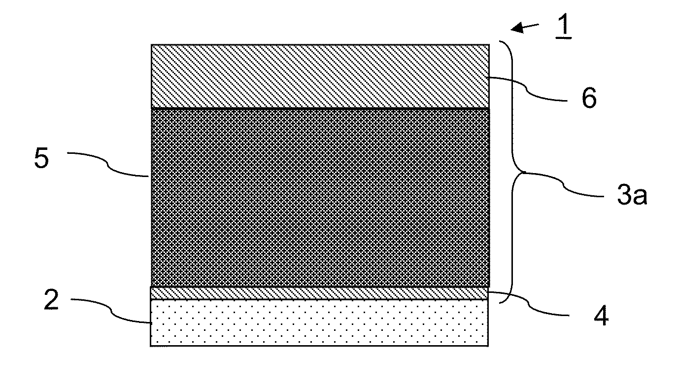
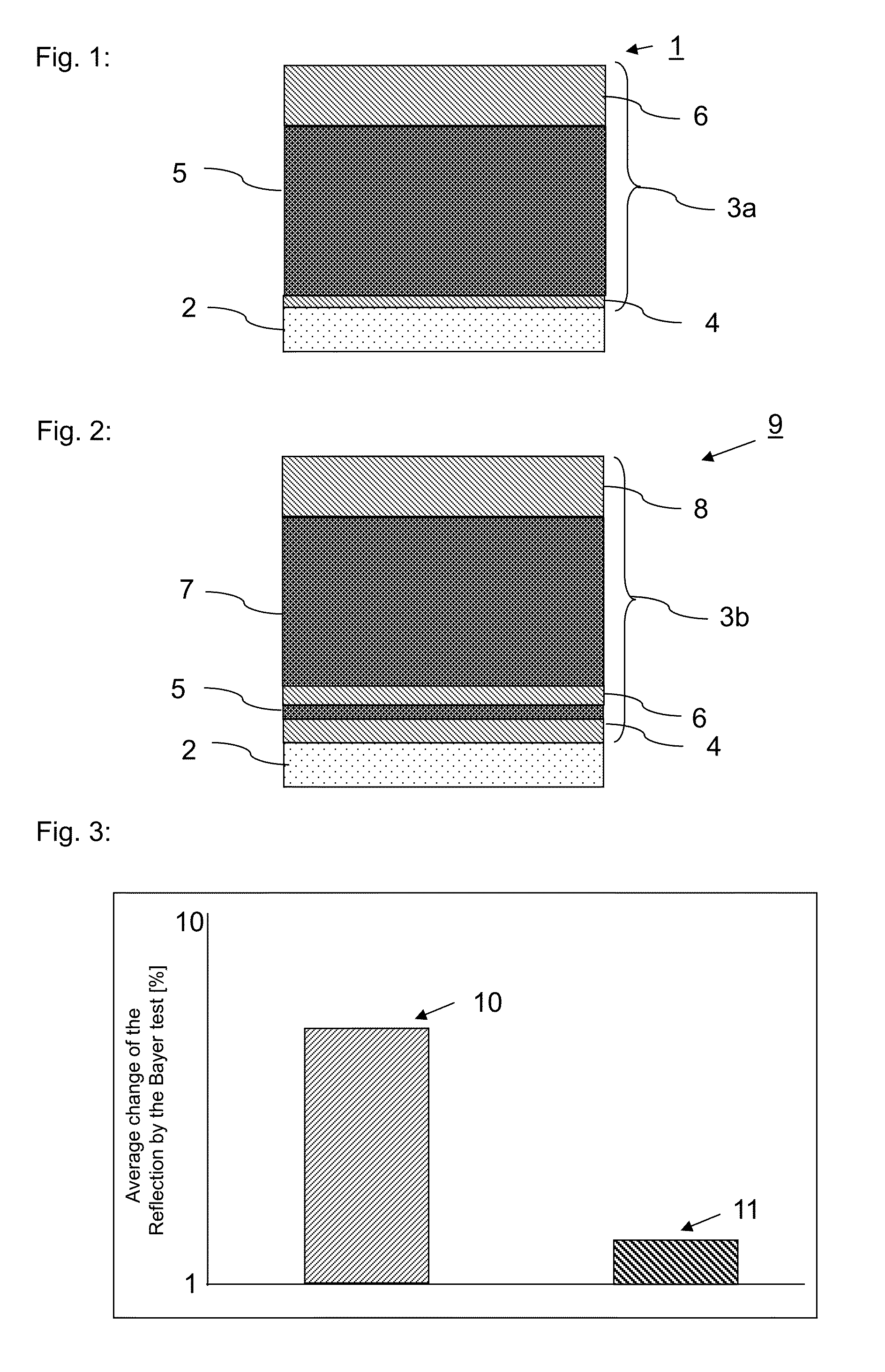
[0089]FIG. 1 schematically shows an exemplary embodiment of a substrate coated according to the invention 1. Here, substrate 2 is coated with a three-layered optical interference coating 3a. Coating 3a comprises layers 4, 5, and 6. Layers 4 and 6 are low refractive index layers, layer 5 is a high refractive index layer. The first low refractive index layer 4 is deposited directly on the substrate 2 and has a layer thickness in a range from 10 to 30 nm. On first low refractive index layer 4, the first high refractive index layer 5 is arranged, which has a layer thickness from 100 to 1000 nm. First high refractive index layer 5 is disposed between the first low refractive index layer 4 and the second low refractive index layer 6. In the embodiment shown in FIG. 1, the second low refractive index layer 6 forms the uppermost layer of coating 3a and has a layer thickness in a range from 60 to 100 nm. Thus, the thickness of the second low refractive index layer 6 is greater than the thick...


PUM

PropertyMeasurementUnit
refractive indexaaaaaaaaaa

Abstract

A coated substrate is provided with a scratch-resistant anti-reflective coating. The anti-reflective coating is designed as an optical interference coating that has at least two low refractive index layers and at least one high refractive index layer. The high refractive index layer is a transparent hard material layer and includes crystalline aluminum nitride with a hexagonal crystal structure with a (001) preferred orientation. The low refractive index layers include SiO2. The low refractive index layers and high refractive index layers are arranged alternately.

Description

CROSS REFERENCE TO RELATED APPLICATIONS[0001]This application claims benefit under 35 U.S.C. §119(a) of German Patent Application No. 102014104798.2 filed Apr. 3, 2014, the entire contents of which are incorporated herein by reference.BACKGROUND[0002]1. Field of the Disclosure[0003]The invention relates to a coated substrate having an anti-reflective coating. More particularly, the invention relates to a coated substrate comprising an anti-reflective coating in form of an optical interference coating. The invention also relates to a method for producing such a coating and to the use of a substrate comprising such a coating.[0004]2. Description of Related Art[0005]Optical interference coatings are used as anti-reflective coatings. Depending on the particular use or application field, these coatings will be exposed to different degrees of mechanical stress. If such coatings are for example used as watch glasses, viewing windows of civil and military vehicles, cooktops, or display cove...

Claims


Application Information

Patent Timeline
Patent Type & Authority Applications(United States)
IPC IPC(8): G02B1/115C23C14/18C23C14/34
CPCG02B1/115C23C14/34Y10T428/24975Y10T428/24942C23C14/185C03C17/34C03C17/3435C23C14/0036C23C14/0641C23C14/35C03C2217/734
Inventor HENN, CHRISTIANDAMM, THORSTENHAHN, ANDREASBRAUNECK, ULF
Owner SCHOTT AG
Why Eureka
Try Eureka