
Thermal process to transform contaminated or uncontaminated feed materials into useful oily products, uses of the process, products thereby obtained and uses thereof, manufacturing of the corresponding plant

a technology of thermal treatment and feed materials, applied in the direction of liquid carbonaceous fuels, special form destructive distillation, coking carbonaceous materials, etc., can solve the problems of requiring extensive laboratory analysis, a threat to the environment, and being abandoned or legislated

Active Publication Date: 2015-12-24
ENVIROLLEA
View PDF11 Cites 14 Cited by
  • Summary
  • Abstract
  • Description
  • Claims
  • Application Information

AI Technical Summary

Benefits of technology

The patent describes a process for thermal treatment of a feed material using a rotating kiln with a positive pressure managing system. The process involves injecting a sweep gas, such as nitrogen or a non-reactive gas, into either the rotating kiln or the feed stream entering it. The conditions of the thermal treatment are managed to ensure that the resulting gas stream after cooling contains at least one liquid phase that is predominantly an oily liquid phase. This process is suitable for heavy oil obtained through a process described in the patent. The technical effect of this patent is the development of a method for efficiently managing the thermal treatment of a feed material to produce heavy oil suitable for various applications.

Problems solved by technology

Waste oils, especially used lubricating oils (ULO), are considered a threat to the environment, and is classified as a hazardous product in most jurisdictions.
Among the processes that regenerate ULO into lubricating oil base-stocks, some, such as the acid clay processes, were abandoned or legislated out because of the disposal costs, both financial and environmental, of the by-products such as spent acid and clays.
Because of their high capital and operating costs, these plants must be close to large population centre and / or serve a large collection area, and usually require government subsidies to be viable.
Again, these applications require extensive laboratory analyses.
The process comprises raising a temperature of a feed mixture of fresh waste oil and a recycled non-volatile residue to a range of 400 to 490 degrees Celsius for a time sufficient to cause pyrolysis of the heavy hydrocarbons contained in the feed mixture, but insufficient to permit substantial undesired polymerization, oxidation and dehydrogenation reactions to take place in the feed mixture; cooling the resulting pyrolized waste oil mixture to a temperature in the range of 300 to 425 degrees Celsius, and maintaining the temperature while allowing volatile components in the pyrolyzed waste oil mixture to evaporate, leaving a non-volatile residue containing the contaminants; condensing the evaporated volatile components to form a reclaimed oil product; and mixing the non-volatile residue with fresh waste oil to form more of the feed mixture and repeating the temperature raising, cooling, evaporation and mixing steps on a continuous basis, while continuing to condense volatile components evaporated from the pyrolyzed waste oil mixture.
Among the problems common to stationary reactors in waste oil applications are coking of the reactor walls, which impedes heat transfer from the heat source to the oil to be treated, and fouling of the equipment, not only in the reactor but also upstream and downstream of the reactor.
Indirectly fired rotating kilns are usually considered inefficient means to convey heat into a reactor.
From a practical point of view, it is difficult to ensure the integrity of the seals of both the main reactor and the coke incinerator when there is a circulating stream of solids.
When produced gas is circulated to heat the reactor feed oil to cracking temperatures, large amounts of circulating gas is required, compared to the fresh feed stream.

Method used


Image

  • Thermal process to transform contaminated or uncontaminated feed materials into useful oily products, uses of the process, products thereby obtained and uses thereof, manufacturing of the corresponding plant
  • Thermal process to transform contaminated or uncontaminated feed materials into useful oily products, uses of the process, products thereby obtained and uses thereof, manufacturing of the corresponding plant
  • Thermal process to transform contaminated or uncontaminated feed materials into useful oily products, uses of the process, products thereby obtained and uses thereof, manufacturing of the corresponding plant

Examples


example 1

With the Injection of 5% Wt. Water Added to the 16 l / h Reactor Feed Oil

[0327]Refer to Table 1—Example 1 for a summary of the operating conditions and feed and products rates and analyses. The waste oil streams tested contained used lubricating oils as well as other oily streams such as metal working oils, transmission fluids, greases, form oils, and any number of unknown waste oil streams.

TABLE 1EXAMPLE 1Reactor Size: L = 1.07 m, Diameter 0.47 mReactor Temperature: 490 C.Reactor Pressure: 124 KPa(a)Sweep Gas: Steam @ 5% Weight on FeedHeavy Oil Recycle: NoneOil Feed Rate: 16 L / hCokeTestMethodUnitsFeed OilGasNaphthaGasoilHeavy Oil& SolidsWeight % on Dry Oil Feed1005.38.056.520.69.6Density @ 15 C.ASTM D4052g / ml0.890.7580.8660.9331.4Molecular Weightg / mole36.7Water (1)STM D1533Volume %5.70.7MetalsDigestion & ICP-ISppm Weight2160324025550SulphurLECO S32Weight %0.630.00370.050.260.912.63HalogensOxygen Bomb Combustionppm Weight47019284.35219Viscosity @ 40 C.ASTM D445cSt33.62.1177.1Copper St...

example 2

Kept the Same Oil Feed Rate and Similar Operating Conditions as in Example 1 but without Water Injection into the Reactor Feed

[0332]Please refer to the Table 2

TABLE 2Example 2Reactor Size: L = 1.07 m, Diameter 0.47 mReactor Temperature: 500 C.Reactor Pressure: 125 KPa(a)Sweep Gas: NoneHeavy Oil Recycle: NoneOil Feed Rate: 16 L / hHeavyCoke &TestMethodUnitsFeed OilGasNaphthaGasoilOilSolidsWeight % on Dry Oil Feed1009.811.246.822.69.6Density @ 15 C.ASTM D4052g / ml0.8930.7580.8650.9331.4Molecular Weightg / mole37.4WaterSTM D1533Volume %0.7MetalsDigestion & ICP-ISppm Weight21603Not25510DoneSulphurLECO S32Weight %0.63Not Done0.050.260.912.63HalogensOxygen Bomb Combustionppm Weight470192855219Viscosity @ 40 C.ASTM D445cSt33.62.177.1Copper Strip CorrosionASTM D1201aSedimentsASTM D2276mg / ml0.50.05Flash PointASTM D92C.12848CCRASTM D189Weight %3.341.01AshASTM D4422 & ASTM D482Weight %0.40.010.057.43pHDistillationASTM D2887Weight %IBPC.1623015033810%C.2464717837450%C.4149825543690%C.528133343525EPC...

example 3

The Oil Feed Rate was Increased by 50% to 24 l / h, Again without Water in the Reactor Feed

[0337]Please refer to the Table 3—Example 3 for a summary of the operating conditions and feed and products rates and analyses.

TABLE 3Example 3Reactor Size: L = 1.07 m, Diameter 0.47 mReactor Temperature: 495 C.Reactor Pressure: 125 KPa(a)Sweep Gas: NoneHeavy Oil Recycle: NoneOil Feed Rate: 24 L / hCokeTestMethodUnitsFeed OilGasNaphthaGasoilHeavy Oil& SolidsWeight % on Dry Oil Feed1000.611.954294.5Density @ 15 C.ASTM D4052g / ml0.8890.7520.8620.9319.0Molecular Weightg / mole37.6WaterSTM D1533Volume %0.7MetalsDigestion & ICP-ISppm Weight86.90.0461(1)SulphurLECO S32Weight %0.630.030.260.882.63HalogensOxygen Bomb Combustionppm Weight47019084.545.2219Viscosity @ 40 C.ASTM D445cSt33.61.8966.3Copper Strip CorrosionASTM D1203bSedimentsASTM D2276mg / ml0.140.60.05Flash PointASTM D92C.12841222 (OC)CCRD189Weight %3.340.87AshASTM D4422 & ASTM D482Weight %0.40.057.43pH4.32DistillationASTM D2887Weight %IBPC.16230144...


PUM

PropertyMeasurementUnit
pressureaaaaaaaaaa
temperatureaaaaaaaaaa

Abstract

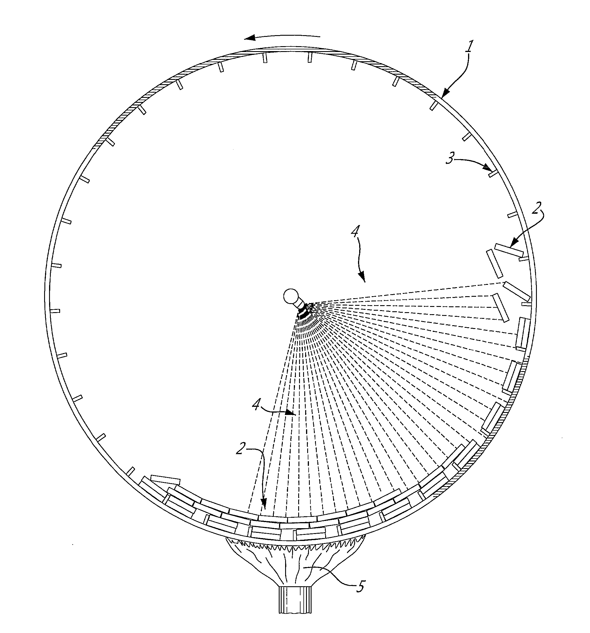
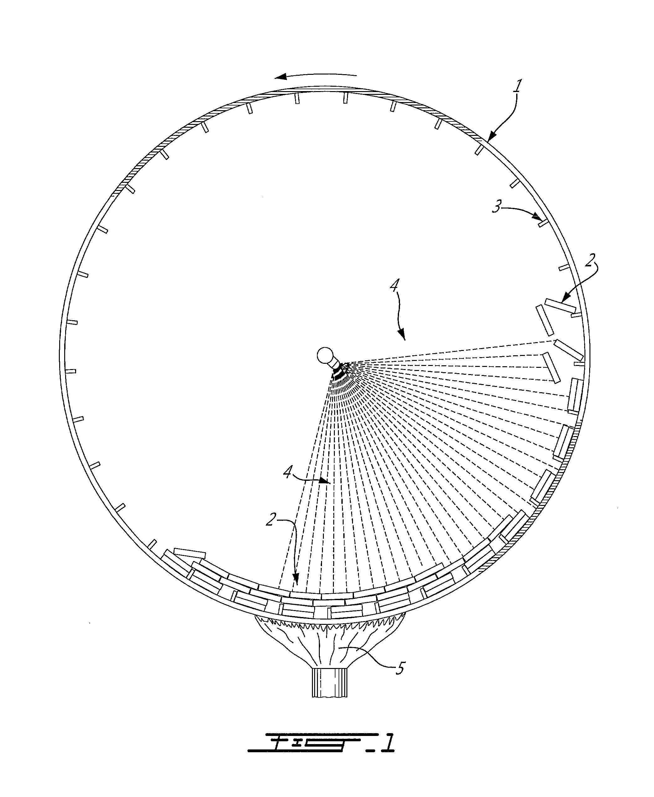
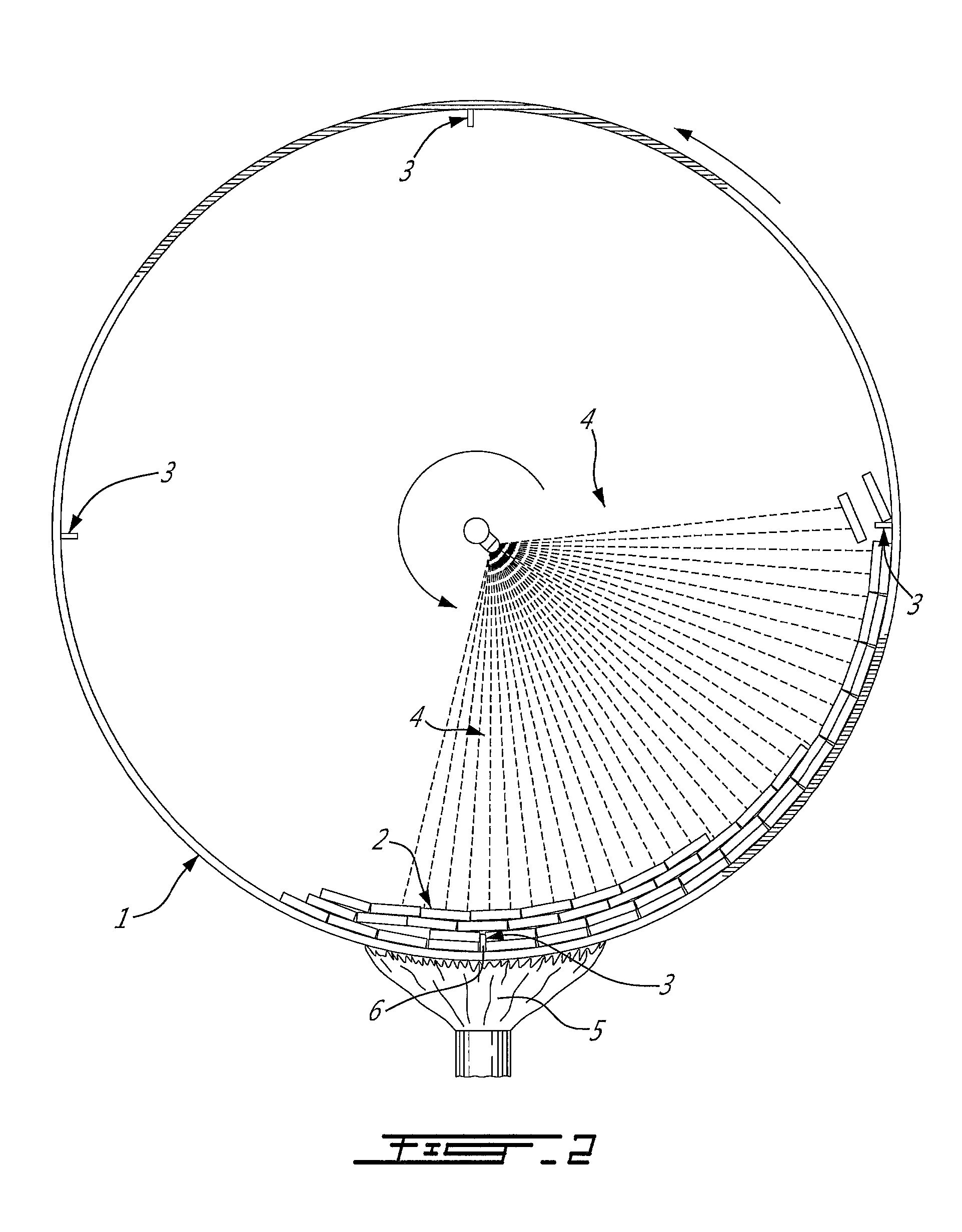
The process is for thermally treating a feed material. The process comprises at least one step performed in a rotating kiln operating under positive pressure with a pressure control system and wherein in the process a sweep gas, that is an inert gas or a substantially non-reactive gas, is injected into the rotating kiln or in the feed stream entering the rotating operating kiln; or at least one step performed in a rotating kiln operating under positive pressure managing system; or at least one step performed in a rotating kiln wherein a sweep gas is injected in the rotating kiln or in the feed stream entering the rotating operating kiln. In step a), or in b) or in step c), the conditions of the thermal treatment are managed in order that the exit stream, after cooling, result in at least one liquid phase that is preferably essentially an oily liquid phase.

Description

FIELD OF THE INVENTION[0001]The invention relates to a process to thermally treat contaminated or uncontaminated feed materials such as contaminated or uncontaminated feed oils, more particularly such as used lubricating oils, waste oils, oily tank bottoms, heavy oils, rubber, plastics, marpol or bitumen, in a rotating kiln operating under pressure and / or with the injection of a gas, preferably with injection of a sweep gas into the reactor or into its feed stream. The treated feed material results after treatment and after cooling in at least one liquid phase that is preferably an essentially oily stream.BACKGROUND OF THE INVENTION[0002]Waste oils, especially used lubricating oils (ULO), are considered a threat to the environment, and is classified as a hazardous product in most jurisdictions. The Environment Protection Agency (EPA) states that: “One gallon of used lubricating oil can pollute a million gallons of water.” There is a need for a viable and flexible process that can de...

Claims


Application Information

Patent Timeline
Patent Type & Authority Applications(United States)
IPC IPC(8): C10G7/00C10G31/06C10B57/04C10B57/08C10B47/30
CPCC10G7/006C10B57/08C10G31/06C10B57/045C10G7/003C10B47/30C10L1/04C10B53/02C10B53/06C10B53/07C10B55/04C10G1/02C10G1/10C10G3/40C10G9/00C10G2300/1003C10G2300/1007C10G2300/1014C10G2300/1018C10G2400/04C10G2400/10Y02P30/20
Inventor WHEELER, LUCIE B.
Owner ENVIROLLEA
Learn More