Method for depositing layer
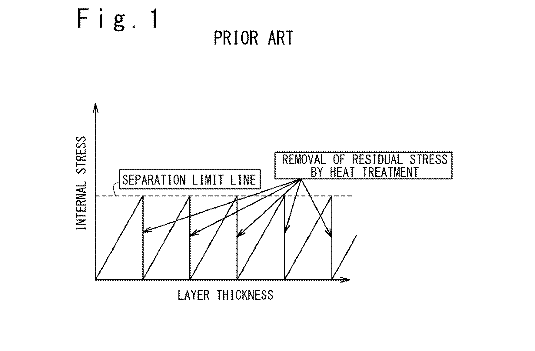
a layer and depositing technology, applied in the direction of metal material coating process, coating, pressure inorganic powder coating, etc., can solve the problem of increasing and achieve the effect of reducing the number of heat treatment and reducing the cost of layer deposition
- Summary
- Abstract
- Description
- Claims
- Application Information
AI Technical Summary
Benefits of technology
Problems solved by technology
Method used
Image
Examples
first embodiment
1. First Embodiment
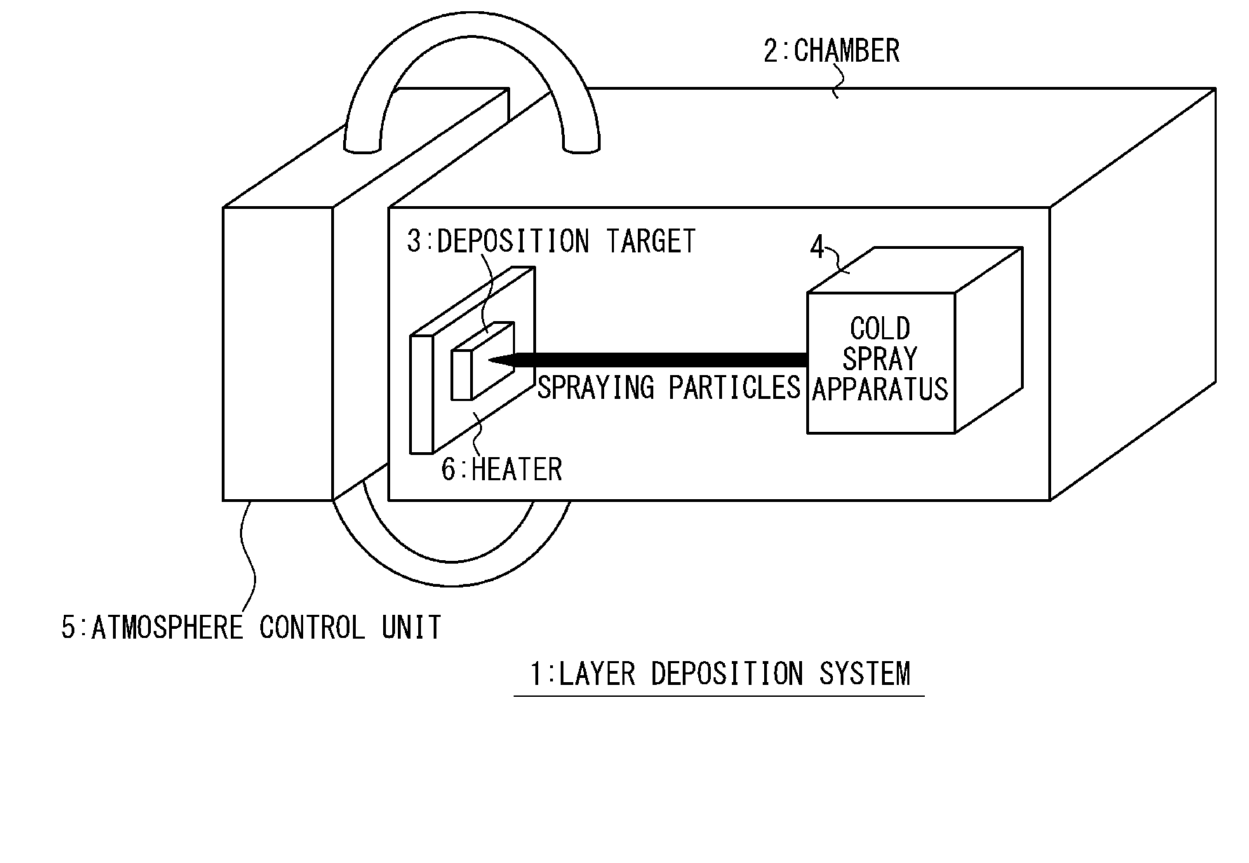
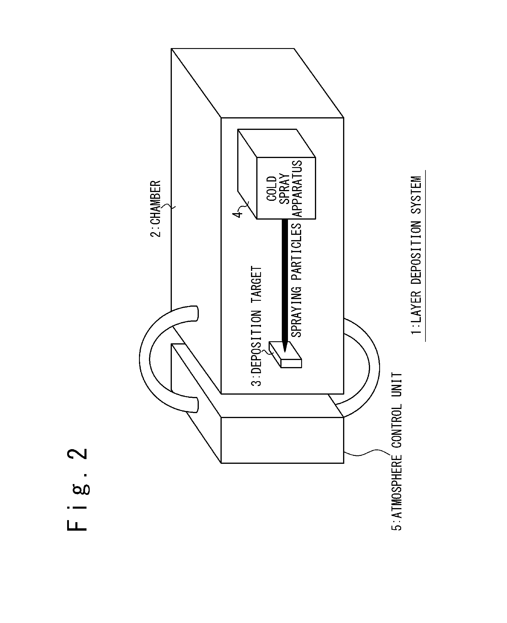
[0034]FIG. 2 schematically indicates the configuration of the layer deposition system 1 according to the first embodiment. The layer deposition system 1 includes a chamber 2, a cold spray apparatus 4, and an atmosphere control unit 5. In the chamber 2 (layer deposition chamber), a deposition target 3 is arranged. The cold spray apparatus 4 is arranged so that it is possible to perform the layer deposition on the deposition target 3 using the cold spray process.
[0035]The atmosphere control unit 5 is arranged for controlling an atmosphere in the chamber 2. In the first embodiment, the atmosphere control unit 5 is a gas supply apparatus for supplying “non-oxidizing gas” into the chamber 2. The non-oxidizing gas is, for example, inert gas such as Ar and He, and nitrogen N2.
[0036]FIG. 3 is the flowchart for indicating the layer deposition method according to the first embodiment. Referring to FIG. 2 and FIG. 3, the layer deposition method according to the first embodim...
second embodiment
2. Second Embodiment
[0054]According to the above-described first embodiment, the atmosphere in the chamber 2 is set to the non-oxidizing gas atmosphere. However, as long as the oxidation is suppressed, the atmosphere is not limited thereto. In the second embodiment, in place of the non-oxidizing gas atmosphere, a vacuum atmosphere is used. In this case, the atmosphere control unit 5 is a pressure reducing unit for making a state in the chamber a vacuum state. The vacuum state is, for example, a state in which the pressure is 1×10⁻³ Pa or less.
[0055]FIG. 5 is the flowchart for indicating the layer deposition method according to the second embodiment. In the second embodiment, instead of above-described Step S2, Step S2′ is performed. In Step S2′, the atmosphere control unit 5 is activated to set the atmosphere in the chamber 2 to the vacuum atmosphere. The rest is the same as the first embodiment.
[0056]According to the second embodiment, the same effect can be obtained as the first e...
third embodiment
3. Third Embodiment
[0057]FIG. 6 schematically indicates the configuration of the layer deposition system 1 according to the third embodiment. The layer deposition system 1 includes the cold spray apparatus 4 and a heater 6. The heater 6 is disposed to be able to heat the deposition target 3, and typically is arranged so as to contact the deposition target 3. The cold spray apparatus 4 is disposed so as to be able to perform the layer deposition on the deposition target 3 by the cold spray process.
[0058]FIG. 7 is the flowchart for indicating the layer deposition method according to the first embodiment. Referring to FIG. 6 and FIG. 7, the layer deposition method according to the third embodiment will be explained. Note that explanations that are duplicative of that provided with respect to the first embodiment are appropriately omitted.
Step S3′
[0059]The heater 6 is activated, and heats the deposition target 3. As a result, temperature of the deposition target 3 becomes higher than ro...
PUM
| Property | Measurement | Unit |
|---|---|---|
| thickness | aaaaa | aaaaa |
| thickness | aaaaa | aaaaa |
| thick | aaaaa | aaaaa |
Abstract
Description
Claims
Application Information
 - R&D
- Intellectual Property
- Life Sciences
- Materials
- Tech Scout
- Unparalleled Data Quality
- Higher Quality Content
- 60% Fewer Hallucinations
Browse by: Latest US Patents, China's latest patents, Technical Efficacy Thesaurus, Application Domain, Technology Topic, Popular Technical Reports.
© 2025 PatSnap. All rights reserved.Legal|Privacy policy|Modern Slavery Act Transparency Statement|Sitemap|About US| Contact US: help@patsnap.com


