Liquid or Hydrate Power System Applied To A Single Point Injection Gas Lift System

Inactive Publication Date: 2015-12-31
BOLLINGHAM LEONARD ALAN
View PDF3 Cites 9 Cited by
  • Summary
  • Abstract
  • Description
  • Claims
  • Application Information

AI Technical Summary

Benefits of technology

The patent describes a system for safely and efficiently producing oil from a well using liquefied gas and compressed gas. The system is designed to be portable and can be easily adapted to different well requirements. It uses a compressor and tank to continuously inject gas into the well, which reduces the pressure needed to produce oil. The system is controlled by a controller that monitors various components and can adjust them accordingly. This design allows for continuous oil production without the need for costly equipment or high pressure. It also helps capture and use greenhouse gases, making it an eco-friendly and economically feasible solution for producing oil from uneconomical wells.

Problems solved by technology

This is incredibly expensive and in most cases must be placed in the well at the time of the original completion whether it is needed or not because doing this is so expensive otherwise.
Onshore wells will not make enough to even consider this form of enhanced production from the conventional methods.
The costs for every other method in the industry are just too high when initial system cost, installation, and constant maintenance are factored in.
These can fail, and are very expensive to replace.
The cost of this maintenance involves lost production for the duration, the labor cost of pulling the pump, lost rig income, and the cost of replacing or rebuilding the pump.
The compressor system or electric motor to run the pump at the surface can be damaged when the subsurface pump is damaged.
All of these facets make any of these options uneconomical.
This cannot be done in the current system that pressures up the annular space and uses pre-pressured valves that pop open at certain pressures.
The annular space is too voluminous to liquify or pressure up, will release the hydrates before they make it from the injection side into the production side of the system, and is not adequately rated for the pressures.

Method used


Image

  • Liquid or Hydrate Power System Applied To A Single Point Injection Gas Lift System
  • Liquid or Hydrate Power System Applied To A Single Point Injection Gas Lift System

Examples


Embodiment Construction

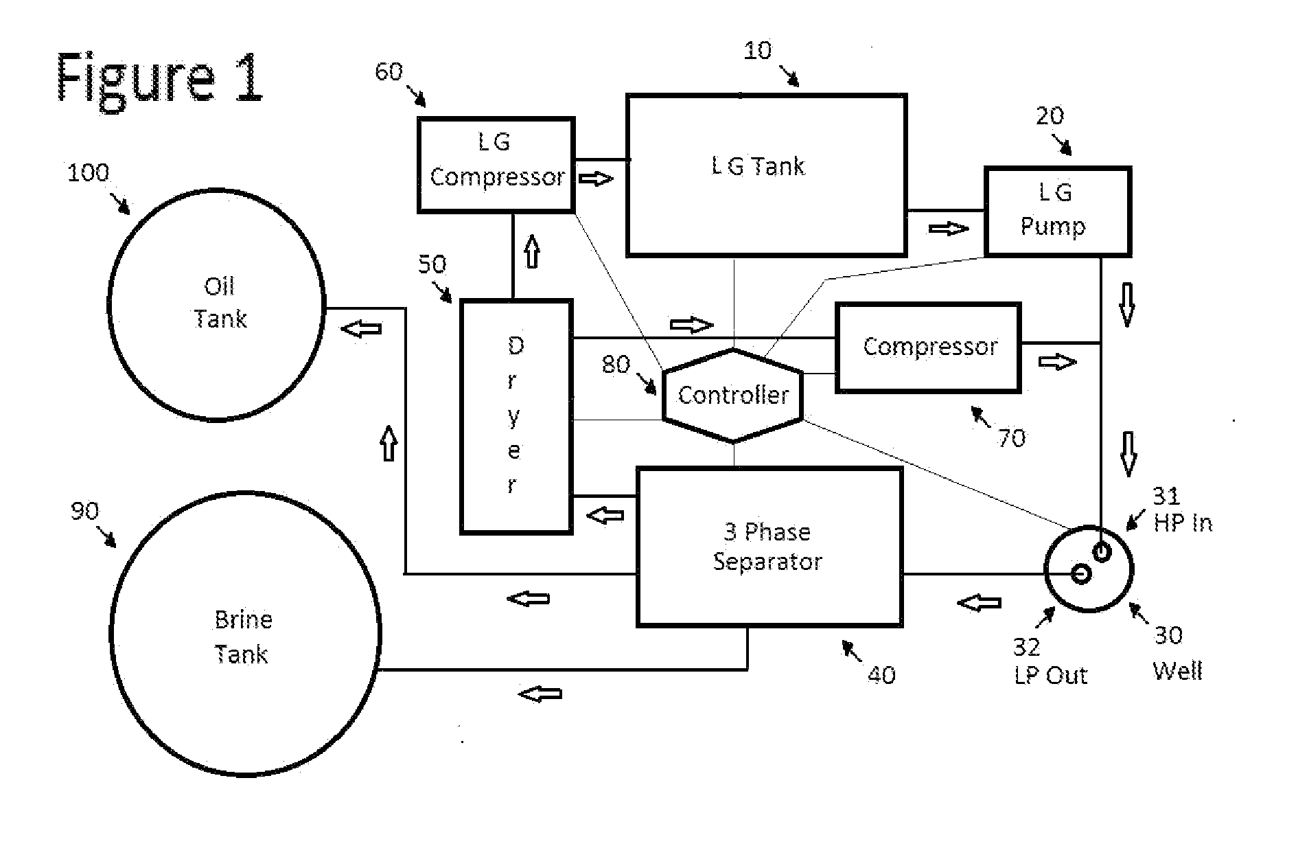
[0037]While the invention is susceptible to various modifications and alternative constructions, certain illustrated embodiments thereof have been shown in the drawings and will be described below in detail. It should be understood, however, that there is no intention to limit the invention to the specific form disclosed, but, on the contrary, the invention is to cover all modifications, alternative constructions, and equivalents falling within the spirit and the scope of the invention as defined in the claims. The patent worthy innovation involves making use of the temperature, pressure, and volume characteristics of phase change in order to improve the production potentials of Gas / Hydrate / Liquids to unload and produce a well by Gas / Hydrate / Liquid expansion or phase change.

[0038]Referring in general to FIG. 1, a gas lift unloading and compression system can be constructed in accordance with the principles of the invention is seen. It is assumed that the down-hole mandrel can be any...


PUM


Abstract

This system stores and uses as needed Compressed Gas, Hydrates, or Liquified Gas to unload and add power in order to produce a well or transfer fluids from one place to another. It can also supply gas to run the system, or generate electricity or various other auxiliary functions. It has been proven successful and could increase production in America and the world by bringing back into production wells that are not economical any other way. One well at a time, or entire fields can be produced with a single compressor. Stripper wells account for 40% of total domestic production. There are 1000s of wells not being produced. Huge production OPEC type wells could be produced with this system better, faster, and less expensive than any other system. This is also environmentally cleaner as very little gas will escape to the atmosphere. I believe that generators and other engines could be operated with this expanding vapor renewable physical reaction which seems close to the level of energy created during the expansion of a diesel chemical reaction.

Description

[0001]When producing a well or transferring fluid, the production system or transfer system stops occasionally resulting in a hydrostatic head loading the well or tubing. Conventional gas lift and liquid lifts use several preset valves or pumps to unload a system of its fluids. This system involves compressing or dropping temperatures or a combination of the two in order to cause sufficient pressure to overcome the hydrostatic head even a change from low pressure gas to hydrates, high pressure compressed gas, or Ia liquid. The hydrates form at a much lower pressure and higher temperature than liquids will form (2500+ psi and 10 degrees Kelvin), and hydrates offer a great point to unload shallow wells around 300 to 600 psi 30 to 60 degrees Fahrenheit.[0002]Hydrates provide a very economical storage and expansion energy production point. Much lower phase change curves than LNG or LP. Therefore, this system can match the pressure of the loaded fluid, or can also match the height with l...

Claims


Application Information

Patent Timeline
IPC IPC(8): E21B43/16E21B47/06E21B43/40E21B43/12
CPCE21B43/168E21B43/122E21B47/065E21B43/385E21B43/40E21B47/07
Inventor BOLLINGHAM, LEONARD ALAN
Owner BOLLINGHAM LEONARD ALAN
Why Eureka
Try Eureka