Systems and methods for welding

Active Publication Date: 2016-01-07
TOYOTA JIDOSHA KK
View PDF1 Cites 8 Cited by
  • Summary
  • Abstract
  • Description
  • Claims
  • Application Information

AI Technical Summary

Benefits of technology

[0031]In so doing, a reliable, accurate, and easy manufacturing process

Problems solved by technology

The use of mechanical clamps during welding, however, leads to inefficiencies in work-piece production.
In particular, mechanical clamping mechanisms require increased time to clamp and unclamp the sheets in position prior to and after welding.
A further disadvantage of conventional apparatus is that the increased clamping time resulting from the use of mechanical clamps inhibits adjustment in the positioning of the sheets which are to be welded together once the clamps are engaged.

Method used


Image

  • Systems and methods for welding
  • Systems and methods for welding
  • Systems and methods for welding

Examples


Example

[0047]Reference will now be made in detail to exemplary embodiments of the disclosure, examples of which are illustrated in the accompanying drawings. Wherever possible, the same reference numbers will be used throughout the drawings to refer to the same or like parts.

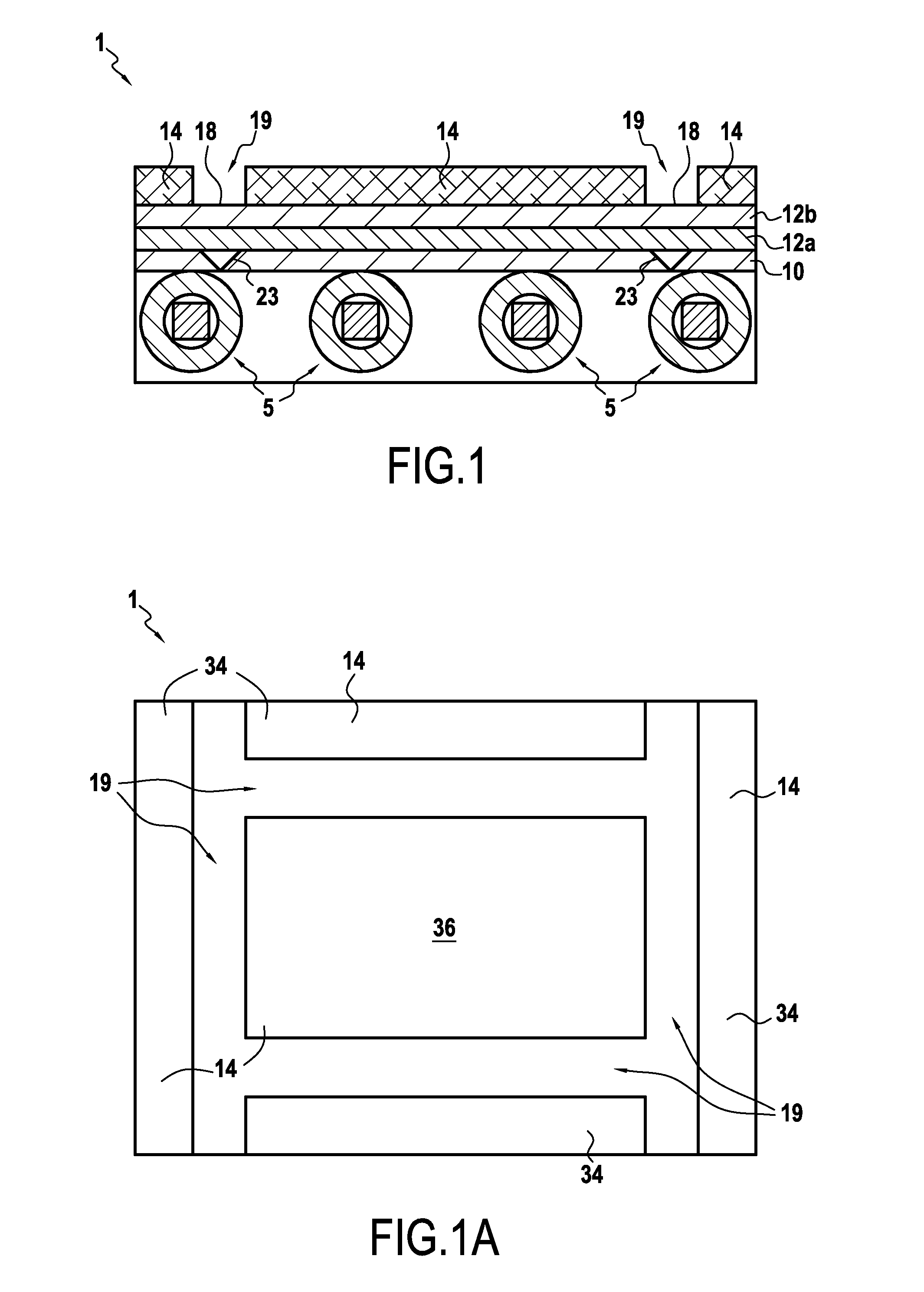
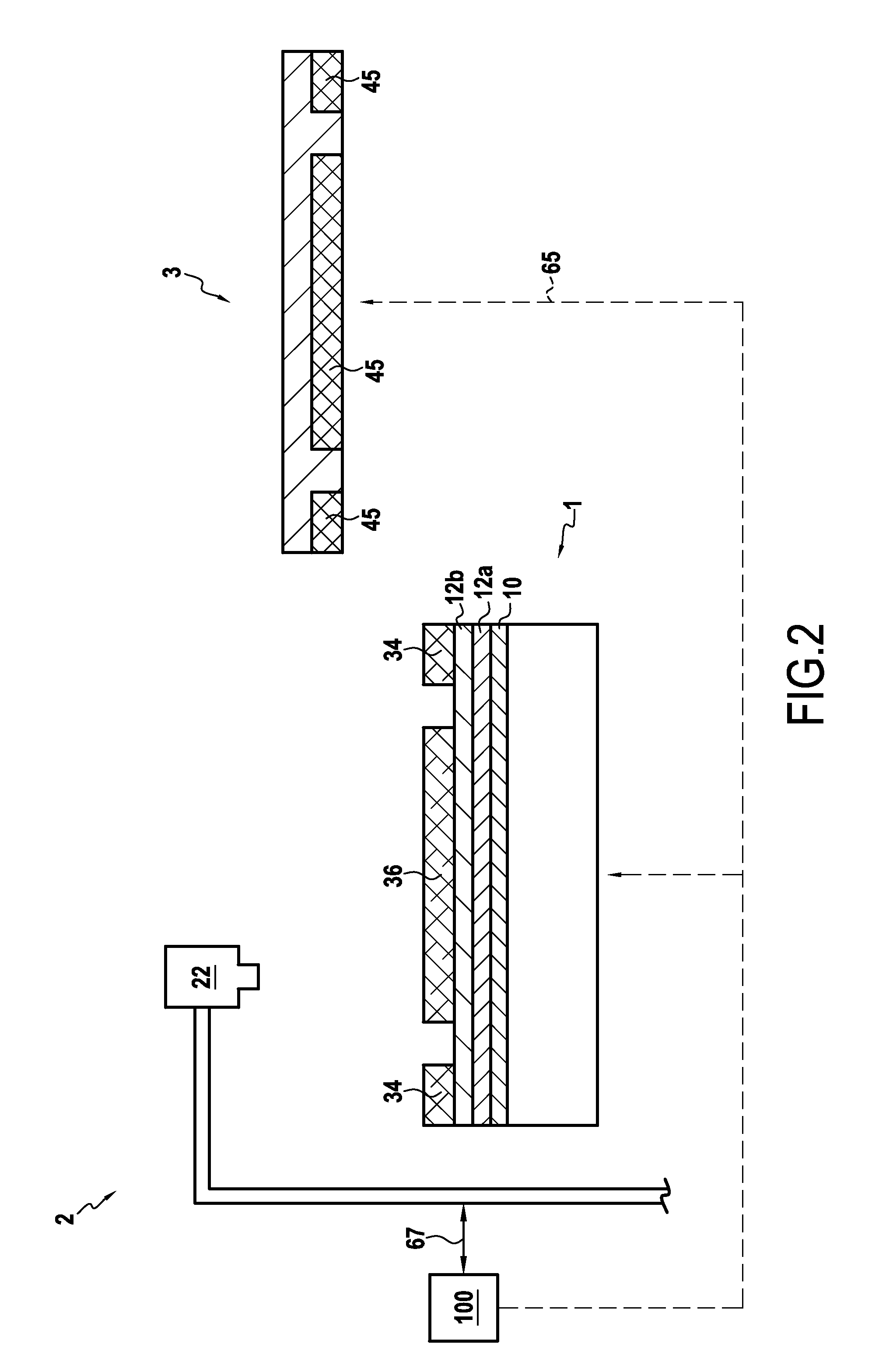
[0048]FIG. 1 shows a cross-sectional view of an exemplary welding fixture 1 for welding at least two sheets of material 12a, 12b, according to embodiments of the present disclosure. Any type of material may be welded, magnetic or not-magnetic, and according to some embodiments of the present disclosure, titanium and titanium alloy sheets having a thickness of less than 1.0 millimeter, preferably less than 0.5 millimeter may be welded.

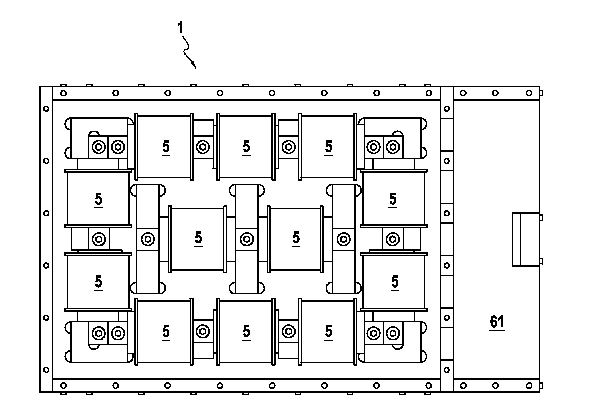
[0049]As shown at FIG. 1, an electromagnet 5 may be provided in proximity to a non-magnetic support 10, which may be configured to receive and support at least two sheets of material 12a, 12b to be welded.

[0050]Electromagnet 5 is configured to receive an electric current and thereby genera...


PUM

PropertyMeasurementUnit
Thicknessaaaaaaaaaa
Thicknessaaaaaaaaaa
Pressureaaaaaaaaaa

Abstract

A welding fixture including an electromagnet, a non-magnetic support configured to receive at least two sheets of material to be welded, and one or more clamping shoes configured to cooperate with the electromagnet to apply a clamping pressure to the at least two sheets of material and the non-magnetic support as a result of a magnetic force produced by the electromagnet is provided. A first of the at least two sheets of material is in contact with at least one of the one or more clamping shoes, and a second of the at least two sheets of material is in contact with at least the non-magnetic support. The one or more clamping shoes being shaped such that a perimeter defined by the one or more clamping shoes is located in the vicinity of a defined weld line to be welded on the at least two sheets of material, the weld line remaining substantially free from optical obstruction during production of the magnetic force.

Description

FIELD OF THE DISCLOSURE[0001]The present disclosure is related to systems and methods for welding, and more particularly to clamping of thin sheets for facilitating a welding operation.BACKGROUND OF THE DISCLOSURE[0002]In manufacturing of electronic devices, e.g., batteries, fuel cells, etc., component design often involves various pieces being assembled together by welding, e.g., two or more thin metal sheets.[0003]Typically, such thin metal sheets are positioned together and placed on a welding support. A welding device (e.g., CO2 high energy laser, electron beam / plasma, arc-welder, and / or other similar devices) can then be used to perform a welding operation.[0004]To obtain an effective and complete weld, it is helpful to ensure that the proximal edges of the objects (e.g., thin metal sheets) to be joined are positioned and immobilized during the welding operation. Such immobilization is often accomplished by way of mechanical clamps, the clamps being anchored to fixtures externa...

Claims


Application Information

Patent Timeline
IPC IPC(8): B25B11/00B23K15/00B23K26/082B23K26/244B23K26/32B23K26/70
CPCB25B11/002B23K15/0026B23K15/006B23K26/082B23K26/244B23K26/32B23K26/702B23K15/0093B23K37/0408B23K37/0435B23K37/047H01F2007/208B23K2101/36B23K2103/14B23K37/04B23K37/00
Inventor EVANS, PAULBLACKBURN, JONATHANRIBTON, COLIN NIGELWOLOSZYN, ANDREW CHRISTOPHER
Owner TOYOTA JIDOSHA KK
Why Eureka
Try Eureka