System and method for joining and hanging ducts

a technology of joining and hanging ducts, applied in the direction of screws, lighting and heating apparatus, heating types, etc., can solve the problems of wasting energy, wasting labor, and destroying gaskets, etc., and achieve the effect of saving labor, saving energy, and being done very quickly

Active Publication Date: 2016-01-07
H J FISCHER
View PDF2 Cites 12 Cited by
  • Summary
  • Abstract
  • Description
  • Claims
  • Application Information

AI Technical Summary

Benefits of technology

[0019]As an additional preferred feature and advantage of the invention, the special configuration of the endmost thread is also operable to prevent, or obstruct or interfere with, re-engagement of the thread with the corner plate. In its simplest form, this special configuration includes a surface on the endmost thread bounding the space between the head and endmost thread, which is at least generally parallel to the opposing surface of the head and is shaped so as to partially obstruct the groove between the endmost thread and the next adjacent thread of the threaded portion of the screw to prevent re-entry of the corner plate into the groove. As another non-limiting example, the endmost thread can extend into the groove toward the next adjacent thread head at a steeper angle than the normal pitch angle of the thread. As another example, the end of the endmost thread can have bulbous or similar shape that prevents re-engagement of the thread, such as a teardrop or partial teardrop shape. As a non-limiting example, to provide the above capabilities, a substantial portion, e.g., 20 to 40 percent of the endmost thread can be generally flat and parallel to the opposing surface of the head, and bounds the space so as to form a bearing surface for opposing forces exerted between the endmost thread and an opposing surface of a corner plate located in the adjacent space, that combined with forces exerted between the opposite surface of the corner plate and the screw head, will be sufficient to hold the screw in the desired substantially perpendicular orientation relative to the corner plate under anticipated conditions, e.g., forces exerted thereagainst by movements of the duct sections for aligning them for assembly.
[0020]According to another preferred aspect of the invention, the pitch of the thread is about equal to the thickness of the respective corner plates measured through the holes, and the holes of the corner plates are shaped, such that the screws can be tilted at a small approach angle relative to the corner plate of the first duct section, and also the alignment axis through the hole therethrough, to engage the thread with that corner plate such that the thread of the screw can pass through the hole of that corner plate without the corner plate itself being pre-threaded or the screw thread forceably cutting a new thread or otherwise deforming a surface of the corner plate adjacent or about the hole. This is also advantageous as it reduces or can virtually eliminate the torque necessary for threading the screw through the plate to save energy when a battery powered driver is used. The insertion is capable of being done very quickly, saving labor. As an additional feature, when the endmost thread has passed or passes through the corner plate, the head of the screw will abut, or be close to and directly face, the surface of the corner plate about or adjacent to the hole, to cause the screw to automatically transition to and maintain the perpendicular orientation relative to the plate even under the lateral loading conditions anticipated to be encountered from relative movements of the duct sections being assembled, so as to be useful as a guide for aligning the duct sections.
[0021]In regard to transitioning of the screw from the tilted to the perpendicular orientation, the endmost thread is configured to be robust so as to accomplish the transition, e.g., with a pivotal or leveraged movement, without bending or breaking, and without application of a substantial force, and the occurrence of the transition can serve to signal the operator of a screw gun or other automatic or powered rotation tool or driver that the screw has achieved the fully engaged position in the corner plate of the first duct section along with the sensation and / or sound that the screw is rotating freely within that corner plate. The change from tilted to perpendicular may also be observed as a visual cue.
[0022]As noted above, when at least one of the large screws is fully received in a corner plate of the first duct section, the screw or screws can be used as a tool or guide for bringing the duct sections into alignment for assembly. As a further aspect of the invention, when the duct sections are aligned, and ready to be assembled, the at least one of the large screws is threadedly engaged with an associated corner plate of the second duct section. This threaded engagement, and that of the subsequently engaged screws, will preferably differ from that with the corner plate of the first duct section in that that the screw will deform or cut a thread in the material of the corner plate of the second duct section in the normal manner of threaded engagement with sheet metal. As a result, the screw threadedly engages the two corner plates in different manners. Regarding the second, the deformation of the second corner plate is advantageous as it allows the corner plates to be brought together in parallel relation, at least as they or the sealant or gasket between the flanges of the mating duct sections are brought into final abutment.
[0023]If it is desired to incorporate a hanger into the assembly at one or more locations, this is easily done by placing a narrow hanger bracket between the corner plates to be fastened together, such that the threaded shank of the associated screw extending from the corner plate of the first duct section extends through a hole in the hanger bracket. The assembler can then simply hold the hanger bracket as the flanges of the duct sections are brought together, or the hole through the hanger bracket can be sized such that the bracket will be self-retained on the threaded shank in a desired orientation by engagement with the screw threads, and the screw rotated in engagement with the corner plate of the second duct section, to clamp the bracket between the joined together corner plates. Non-limiting examples of suitable hanger brackets include sheet metal brackets configured for attachment to a conventional threaded rod, and a radiused element to be partially encircled by a cable. If desired, additional Tek or other sheet metal screws can then be threaded through the mating flanges of the duct sections in close proximity to the bracket, to deform one or both of the flanges about the bracket to capture it and ensure a complete seal thereabout. As another option, one or more of the corner plates can include a feature or element configured for attachment or connection to a hanger, such as a rod or cable, to allow hanging the associated duct section prior to, during or after assembly with the other duct section.
[0024]According to another preferred aspect of the invention, the large screws can include a variety of tips on the shanks of the screws. As a non-limiting example, a tapered or pointed, non-threaded and non-drilling tip can be provided on the screw, configured to serve as a pilot received in a pre-existing hole in the inserted corner plate of the second duct section when in aligned opposing relation to the hole in the inserted corner plate of the first duct section when the duct sections are aligned or in mating relation. As another non-limiting example, the screw can have a more blunt self-drilling tip, in the manner of a hollow hole cutting drill or trepanning bit, so as to have the capability of both drilling through the flanges of both duct sections and serving as a pilot for aligning purposes. As still another non-limiting alternative, the screw can have a conventional spade type or tapered threaded tip typically found on commercially available Tek screws for sheet metal applications. For the latter two examples, an existing hole through an inserted corner plate can be used as a drill guide, for controlling location of additional holes through a flange or flanges, or associated corner plate to prevent walk-off when drilling.

Problems solved by technology

A sticky adhesive gasket is typically adhered to one duct section and if the gasket is adhered to the other section while the sections are improperly or mis-aligned, the gasket is often difficult to detach and can be ruined, requiring removal and application of a new gasket, which is costly and time consuming.
Disturbing the gasket causes openings and creates leakage problems.
If this happens, more time and costs are incurred to repair the leaks adding to time required and worker frustration.
A problem encountered when attempting to avoid premature adhesion is that the drift pins, while useful for general aligning, because of their tapered shape and the presence of the gasket between the duct sections, typically do not facilitate final close alignment of the duct sections for final assembly, and provide little or no ability to hold the duct sections apart while not yet fully aligned to allow workers to manually align the duct sections, such that unintentional gasket contact and adhesion can occur.
Application of adhesive tape gasket is cumbersome as the tape is more readily applied with the duct section placed on the floor or ground in a vertical position with one flanged end down and the end to which the tape gasket is to be applied up.
To apply the tape with the duct section horizontal risks the tape falling off the flange if adequate adhesion isn't achieved, e.g., due to an unclean surface or during cold conditions where the adhesion is poor, etc.
This problem is worsened at the tightly bent portions of tape placed around the inserted corner plate area.
The tape gasket has a certain amount of memory for successful gasket performance requirements which adds to the possibility of movement and loosening especially at the bent areas of the gasket.
Observed shortcomings of this manner of final duct assembly include that the component parts are costly and must be maintained in inventory, it requires substantial labor, and is time consuming.
There is also an attendant possibility of danger when assembly is done at ceiling level, of dropping component parts, so as to injure persons or equipment below.
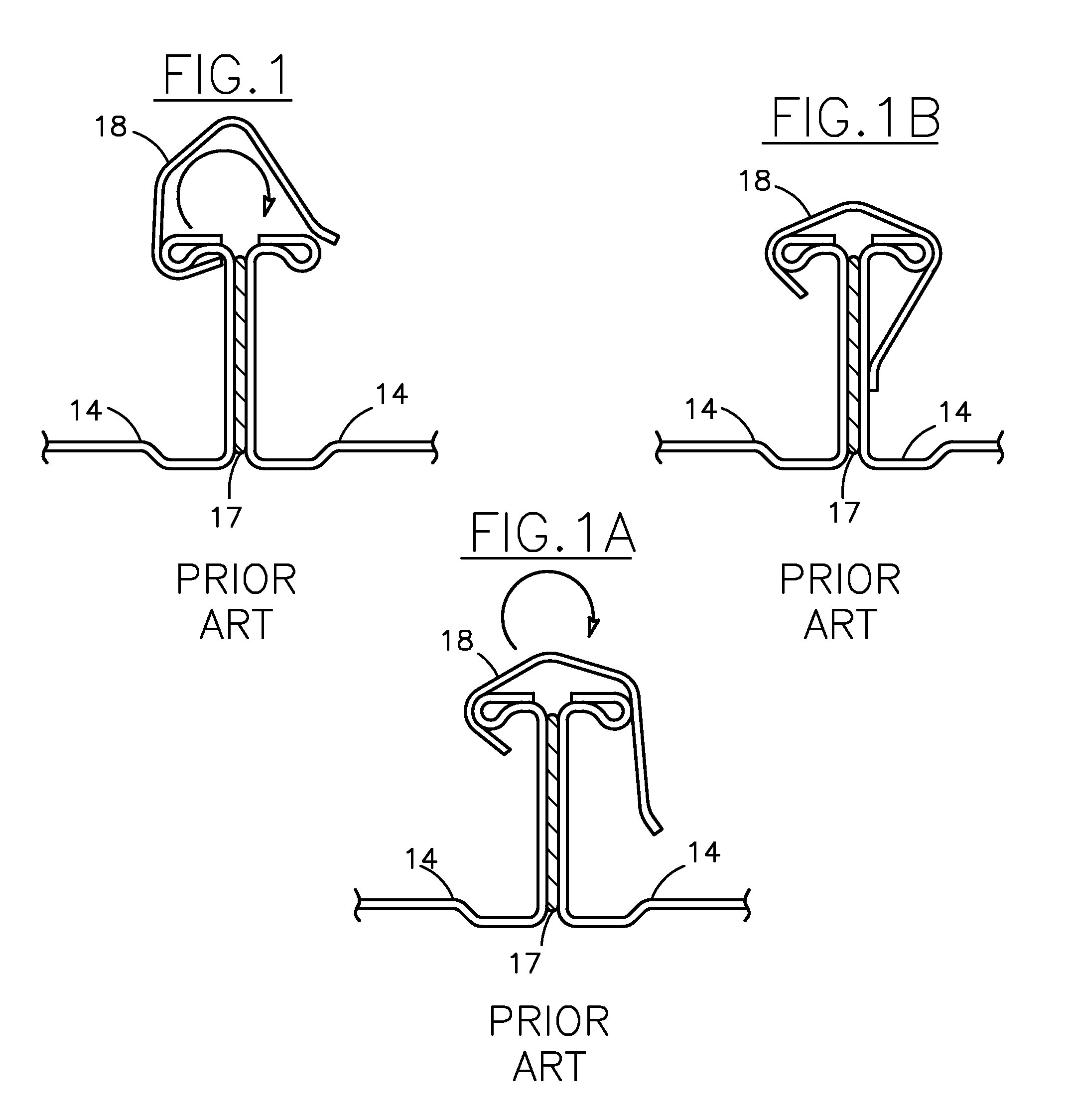
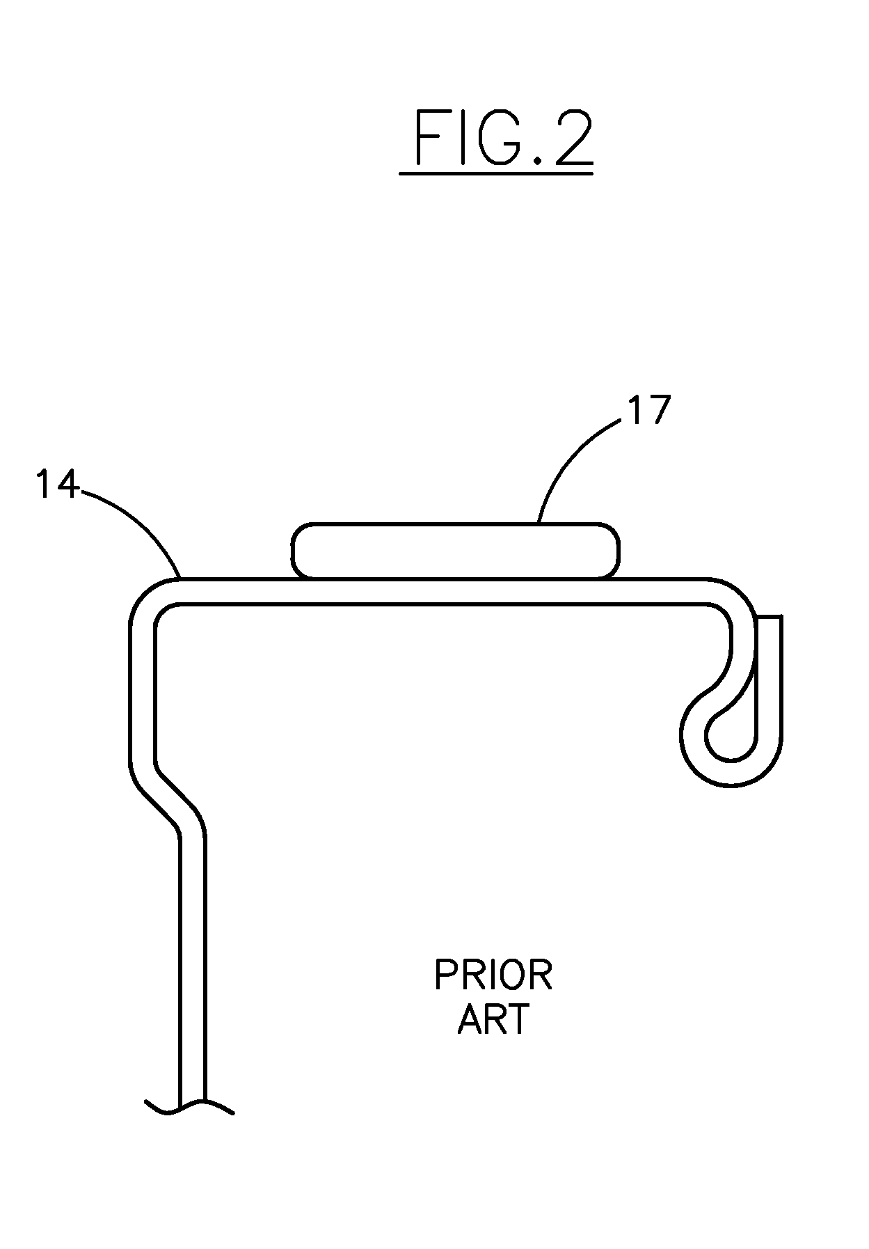
In this latter regard, conventional known clips used to clamp the flanges are known to slide down and fall from the ducts.
However, presently when using Tek screws, it is still required to have the mating flanges clamped or otherwise forceably held together.
Shortcomings of fastening in this manner include that it is imprecise, and if the space between the head of the fastener and the endmost thread is too small to accommodate the closer flange, part of the threads will still have to be obliterated, and if the space is greater than the thickness of the two flanges and any gasket or sealant between them, the fastener may not bring the flanges close enough together to achieve the required seal.
As another possible shortcoming, use of battery operated tools is currently popular for assembling ducts, and if the fastener is threadedly engaged with the flanges using a battery operated driver, the energy consumed to provide the torque required to rotate the fastener while threadedly engaged with the two flanges, and to obliterate the metal threads, will shorten battery life, requiring additional batteries, more frequent charging and related inconvenience and expense.
As an observed shortcoming of use of hanger cables wrapped directly about the ducts, it has been found that normal operational vibration of the duct can cause the cable to “saw” or “cut” into the duct walls resulting in the problem of leakage.
However, with the current manner of duct assembly involving steps of aligning and bringing together with drift pins, clamping, removing the drift pins, then inserting bolts through the holes, it would be difficult to incorporate addition of hangers, as inserting them between clamped flanges would be difficult, and they would have to be blindly aligned with the holes through which the bolts are inserted.
If it is attempted to place the hangers on the drift pins prior to assembly, there is nothing to hold the hangers on the smooth tapered length of the drift pins, and the weight of the hangers can cause the drift pins to tilt down and increase the difficulty of properly aligning the duct sections.
There is the possibility of placement of the hangers on the ends of the bolts after passage through the crimped flanges and the inserted corner plates, but then the hangers may interfere with crimped edges of the associated flanges, and / or require an additional nut for securing.
The crimp may also be poorly done and loosen under load.
In this regard, scheduling duct section lifting and hanging is often also difficult due to other job site work, e.g., presence of contractors such as plumbers, electricians and others needing the same work space.

Method used


Image

  • System and method for joining and hanging ducts
  • System and method for joining and hanging ducts
  • System and method for joining and hanging ducts

Examples


Embodiment Construction

[0109]Referring to the drawings wherein like numerals refer to like parts, FIG. 1 illustrates a typical prior art duct flange connection as currently practiced showing a clip 18, a gasket 17 and duct section end flanges 14. FIG. 1A teaches applying the clip 18 by rotating it into position over and around the flanges 14 as illustrated by the arrow. FIG. 1B shows the clip 18 in a final holding position about the flanges 14.

[0110]FIG. 2 gives the information needed to place the gasket tape 17 properly on the duct section flanges 14. FIG. 3 and FIG. 3A illustrate the typical adhesive tape 17 used for duct joining and shows the non-stick paper backing 20 provided with the tape 17. As the tape 17 is unwound and applied the paper 20 must be crumpled together or otherwise disposed of.

[0111]FIG. 4 shows the tape 17 applied to the end of a duct section flange 14 with a lap 39 where the end of the tape 17 starts and stops. Inserted corner plates 21 are shown in place in the duct section end fl...


PUM

PropertyMeasurementUnit
lengthaaaaaaaaaa
thicknessaaaaaaaaaa
angleaaaaaaaaaa

Abstract

A system and method of assembling flanged duct sections, using large sheet metal screws through opposing inserted corner plates. The large screws are threadedly inserted fully through the corner plates of a first duct section and hold perpendicular thereto for guiding alignment with the mating duct section. The screws hold the duct sections apart to allow aligning them without fluid sealant or tape gasket material on one of the duct sections contacting the other. The screws are then threadedly engaged with the corner plates of the mating duct section, bringing the duct sections together with a leak resistant seal therebetween. Optional hanger brackets can be placed between the corner plates before assembly, and additional screws used to deform the flanges and corner plates about the brackets to compress the sealant or gasket thereabout.

Description

[0001]This application is submitted under 35 U.S.C. 371 claiming priority to PCT / US2014 / 12738, filed Jan. 23, 2014, which application claims the benefit of U.S. Provisional Application No. 61 / 757,005, filed Jan. 25, 2013.TECHNICAL FIELD[0002]This invention relates generally to a system and method for joining and hanging ducts, and more particularly, for assembling duct sections into larger ducts using inserted corner plates, and hanging the duct sections by connection to the corner plates.BACKGROUND ART[0003]PCT patent application Serial No. PCT / US2014 / 12738, filed Jan. 23, 2014; and U.S. Provisional Application No. 61 / 757,005, filed Jan. 25, 2013, are incorporated herein by reference in their entirety.[0004]It is well known in the HVAC (Heating, Ventilating, and Air Conditioning) industry that manufacturing improvements in Mechanical Contractor duct shops have been highly automated through the use of automatic plasma cutting tables for making fittings, automatic coil processing lin...

Claims


Application Information

Patent Timeline
Patent Type & Authority Applications(United States)
IPC IPC(8): F16L23/14F16L23/18F16L25/00
CPCF16L23/14F16L25/0009F16L23/18F24F13/0254F16B35/048
Inventor FISCHER, HERBERT, J.
Owner H J FISCHER
Why Eureka
Try Eureka