Coupler for soil nail and method of emplacing same

Active Publication Date: 2016-01-14
R&B LEASING
View PDF6 Cites 4 Cited by
  • Summary
  • Abstract
  • Description
  • Claims
  • Application Information

AI Technical Summary

Benefits of technology

The invention provides a coupler for soil nails that can be used to connect different sections of soil nails together. The coupler has projections that serve multiple purposes, including centering the soil nail within a drilled hole, providing mixing for grout, and creating a larger diameter hole to increase bond strength. The projections can be adjusted to enlarge the drilled hole and increase the surface area available for grout to bond to the soil nail. This coupler design also allows for a larger diameter hole without needing to re-drill, reducing the time and cost of installation. The enlarged hole also provides greater corrosion protection for the soil nail. Overall, the invention provides a more efficient and cost-effective way to install soil nails.

Problems solved by technology

One particular concern for installation of all soil nails is the potential for corrosion to damage the nails.
Most soil nails are coated with a protective coating; however, over time, considerable forces are applied to the nail along with corrosive chemicals in the soil / rock that will ultimately corrode the soil nails.
Particularly for geological formations such as landslide areas, the soils within these formations tend to be more corrosive than underlying rock layers.
It is undesirable for the projections to generate excessive force in contact with the surrounding earth that would prevent the soil nail from being efficiently advanced to the desired depth.
Therefore in another embodiment, the projections may incorporate a frangible joint that enables a portion of the projections to break away in the event the coupler reaches a layer of earth that is of a predetermined or known density, and it is known that the earth may present an obstacle for the coupler to the extent the coupler and / or the soil nails may be damaged.

Method used


Image

  • Coupler for soil nail and method of emplacing same
  • Coupler for soil nail and method of emplacing same
  • Coupler for soil nail and method of emplacing same

Examples


Embodiment Construction

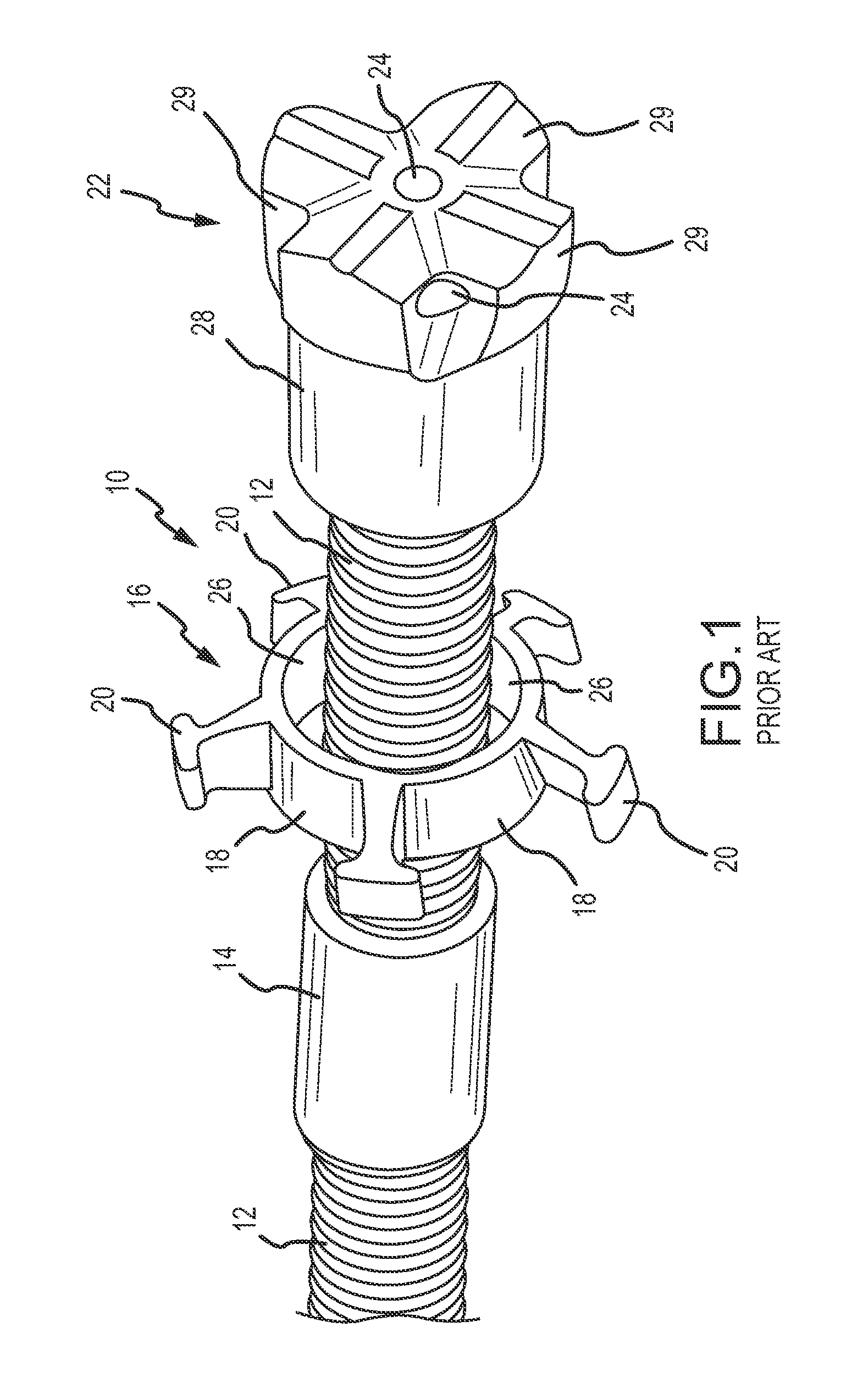
[0038]FIG. 1 illustrates a prior art soil nail assembly 10. The assembly 10 includes a coupler 14 that interconnects adjacent ends of two soil nail sections or pieces 12. The distal end of the assembly has a sacrificial drill bit 22 secured to a distal end of the second soil nail section 12. The drill bit includes a hollow body 28 that is threadably connected to the distal end of the second soil nail section 12. A cutting portion 29 of the drill bit is formed by a plurality of cutting edges. A centralizer 16 is mounted over the second soil nail section, and is used to center the assembly 10 within the drilled hole. The centralizer has a retaining ring 18 and a plurality of spacers 20 that extend radially outward from the retaining ring 18. As shown, the spacers 20 may have a “T” shape. The interior surface 26 of the retainer ring 18 defines an inner diameter that is smaller than the diameter of the exterior surface of the coupler 14. This inner diameter is also smaller than the diam...


PUM


Abstract

A coupler interconnects adjacent sections of soil nails to extend the lengths of the nails. The coupler includes projections extending from the exterior surface of the coupler. The projections serve multiple purposes. One purpose is to center the soil nail within a drilled hole.Another purpose is to provide mixing for amounts of drilled material to remain within the hole, and / or evacuation of drilled material to be removed from the hole. Another purpose is to create a drilled hole with varying diameters in response to different geological layers encountered during drilling. The coupler may include a plurality of ports or openings formed in the body of the coupler enabling injected material such as grout to be further mixed by the rotating action of the coupler during use. The invention further includes a soil nail assembly and a method for installing a soil nail assembly including couplers with projections.

Description

CROSS REFERENCE TO RELATED APPLICATIONS[0001]This application is a continuation-in-part application of U.S. Ser. No. 14 / 327,132, entitled “Coupler for Soil Nail and Method of Emplacing Same” filed on Jul. 9, 2014, the entire disclosure of which are hereby incorporated herein by reference.FIELD OF THE INVENTION[0002]The invention generally relates to subsurface supports placed in the ground, and more particularly, to a coupler for interconnecting adjacent sections of a soil nail assembly, and a method of emplacing the soil nail assembly into the ground.BACKGROUND OF THE INVENTION[0003]Passive supports such as footers, piles, and caissons are well known subsurface supports for many man-made structures such as bridges, buildings, and the like. These supports may be characterized as “passive” because the earth surrounding the supports must first shift or move to mobilize the available tensile, bending, and / or shear capacities of the supports.[0004]In addition to passive subsurface suppo...

Claims


Application Information

Patent Timeline
IPC IPC(8): E02D5/80E02D5/56F16B37/00
CPCE02D5/801F16B37/00E02D5/56
Inventor BARRETT, COLBYBEARD, NATHANRUCKMAN, TIMOTHY ALLENBIRCHMIER, MATTHAMILTON, TODDPETERSEN, JUSTINHAYES, DERRICK
Owner R&B LEASING
Why Eureka
Try Eureka