Distribution analyzing device and distribution analyzing method

a technology of distribution analysis and analysis device, which is applied in the direction of magnetic measurement, instruments, computing, etc., can solve the problems of low signal-to-noise ratio (s/n), the limitation of the miniaturization of the magnetic field sensor, and the inability to manufacture a magnetic field sensor of 100 nm or less in size. achieve the effect of high speed

Active Publication Date: 2016-01-21
KIMURA KENJIRO
View PDF4 Cites 5 Cited by
  • Summary
  • Abstract
  • Description
  • Claims
  • Application Information

AI Technical Summary

Benefits of technology

[0041]According to the present invention, a magnetic field distribution and an electric field distribution are analyzed at high speed even if a sensor sensing area is small.

Problems solved by technology

There is, however, actually a limit to the miniaturization of the magnetic field sensor.
For example, it is hard to manufacture a magnetic field sensor of 100 nm or less in size.
Besides, a miniaturized magnetic field sensor outputs a small electric signal from a sensor sensing area thereof, and suffers a low signal to noise ratio (S / N).

Method used


Image

  • Distribution analyzing device and distribution analyzing method
  • Distribution analyzing device and distribution analyzing method
  • Distribution analyzing device and distribution analyzing method

Examples


embodiment 1

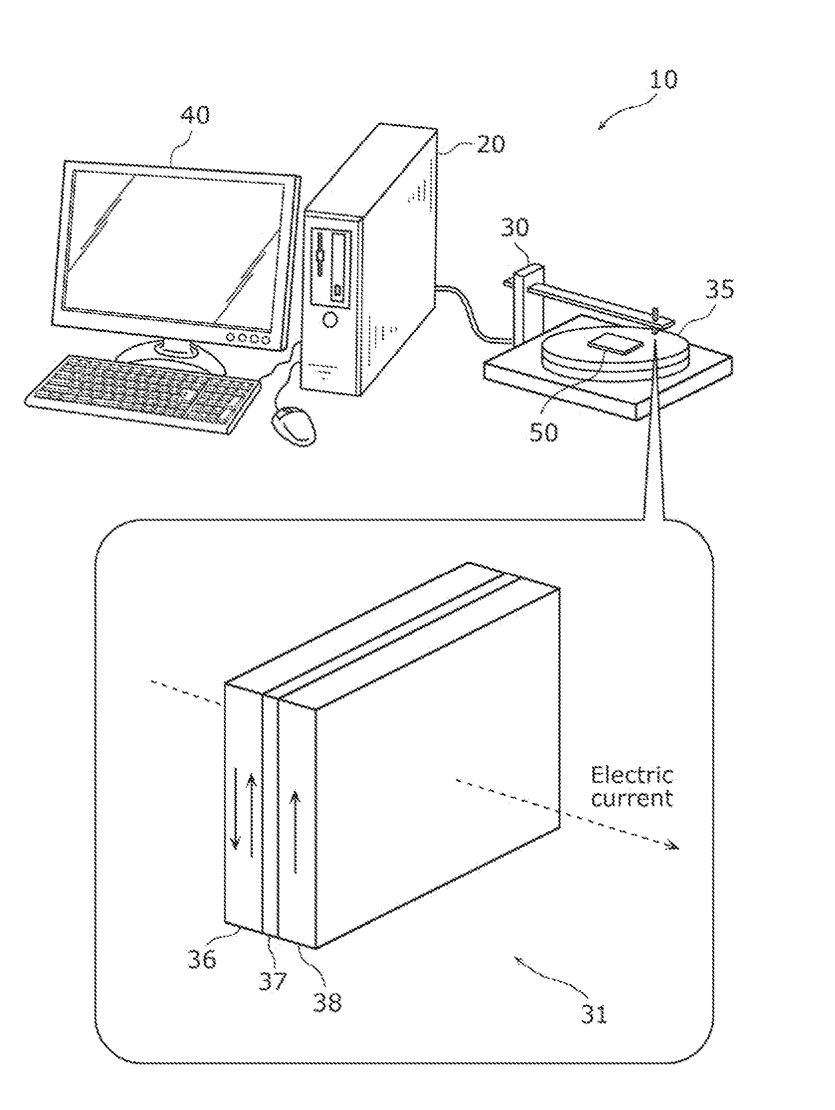
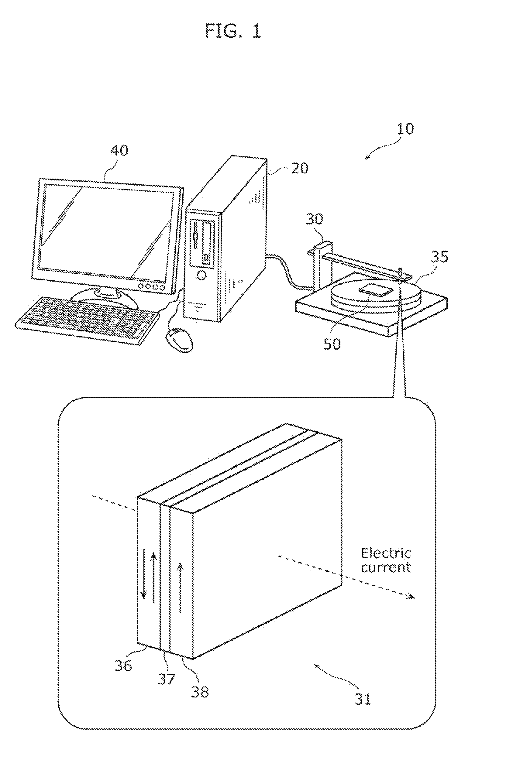
[0058]FIG. 1 is a schematic diagram of a distribution analyzing system according to Embodiment 1. A distribution analyzing system 10 illustrated in FIG. 1 includes a distribution analyzing device 20, a measurement device 30, and a display device 40. The measurement device 30 measures a field to be analyzed. The distribution analyzing device 20 analyzes a distribution of the measured field. The display device 40 displays an image showing the analyzed distribution. The distribution analyzing device 20 and the display device 40 may constitute a computer system, as illustrated in FIG. 1.

[0059]Here, a field to be analyzed has a property satisfying the Laplace equation. The Laplace equation is represented by one of the equations shown in Expression 1.

[Math.10]∂2∂x2F(x,y,z)+∂2∂y2F(x,y,z)+∂2∂z2F(x,y,z)=0∇2F(x,y,z)=0ΔF(x,y,z)=0Expression1

[0060]In Expression 1. F(x, y, z) is a function satisfying the Laplace equation, and is also referred to as a “harmonic function”. Moreover, Δ in Expression...

embodiment 2

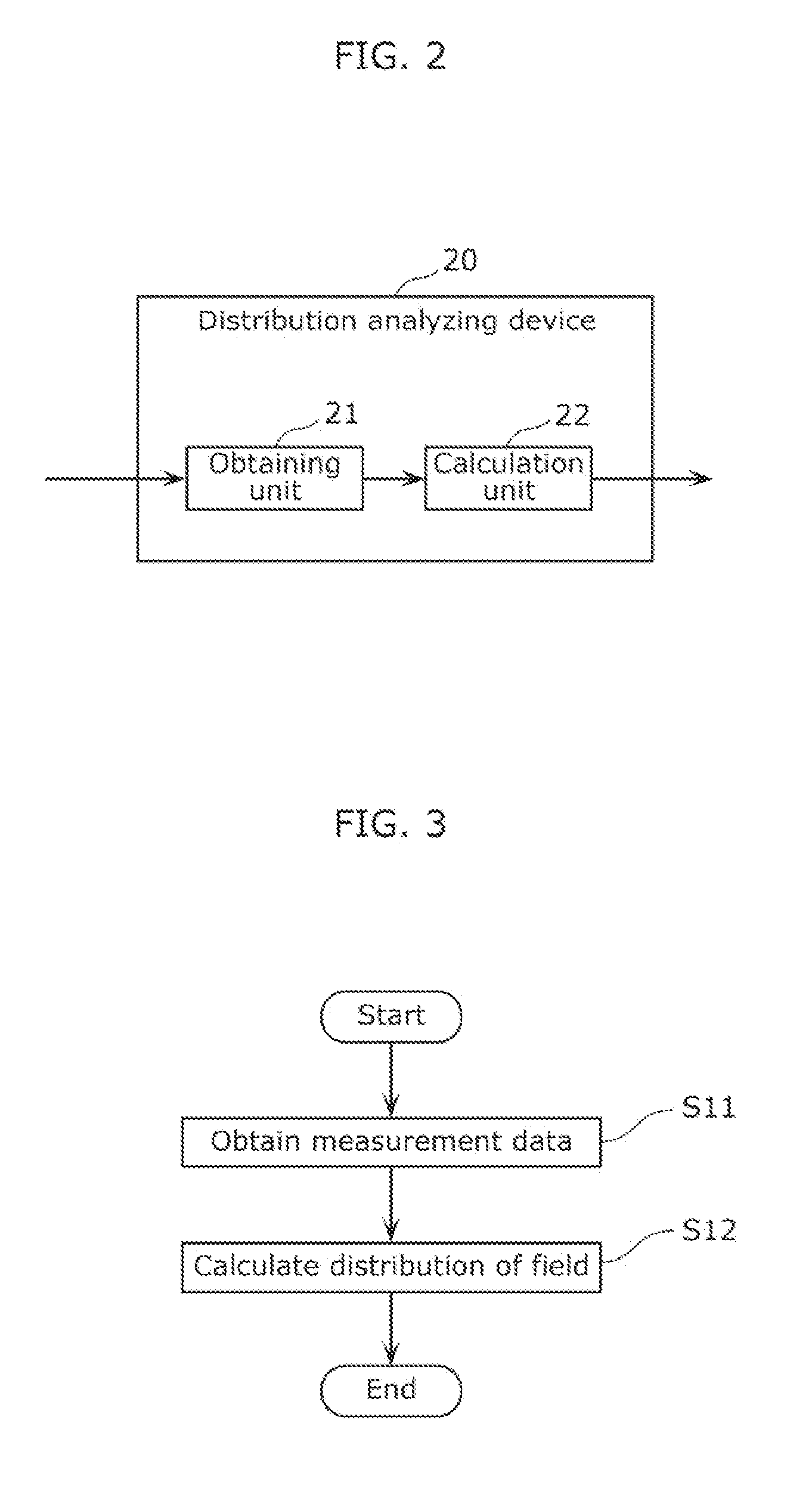
[0139]FIG. 13 is a configuration diagram of a distribution analyzing device according to the present embodiment. A distribution analyzing device 25 illustrated in FIG. 13 includes an obtaining unit 21, a calculation unit 22, a measurement unit 26, and an image processing unit 27. Specifically, the distribution analyzing device 25 according to the present embodiment includes the measurement unit 26 and the image processing unit 27 in addition to the units included in the distribution analyzing device 20 according to Embodiment 1.

[0140]The measurement unit 26 includes a sensor sensing area. Then, the measurement unit 26 measures a distribution of a field through the sensor sensing area. The obtaining unit 21 obtains measurement data from the measurement unit 26. For example, the measurement unit 26 includes a sensor or a probe, for instance. The measurement unit 26 may be the measurement device 30 according to Embodiment 1. Then, the measurement unit 26 may perform equivalent operatio...


PUM


Abstract

A distribution analyzing device (20) includes: an obtaining unit (21) which obtains measurement data of a field measured, through a sensor sensing area, independently at each of rotation angles and at each of grid coordinate positions of the sensor sensing area; and a calculation unit (22) which calculates a distribution of the field from the measurement data, using an arithmetic expression obtained by deriving a target harmonic function, which indicates the distribution of the field, using a condition that a convolution of the target harmonic function and a shape function, which indicates a shape of a cross section of the finite sensor sensing area along a plane parallel to the measurement plane, is equal to a provisional harmonic function derived by solving the Laplace equation using the measurement data and a size of the sensor sensing area in a direction perpendicular to the measurement plane.

Description

TECHNICAL FIELD[0001]The present invention relates to a distribution analyzing device and a distribution analyzing method for analyzing a field having a property satisfying the Laplace equation.BACKGROUND ART[0002]Conventionally, a spatial distribution of a magnetic field (hereafter, also referred to as a “magnetic field distribution”) is utilized in various applications such as locating an abnormal electric current path in an electronic component and examining a disease part of a human body. A superconducting quantum interference device and a magnetoresistive sensor, for instance, are used as magnetic field sensors to measure such a magnetic field distribution. The superconducting quantum interference device is also referred to as a “SQUID element”.[0003]Magnetic force microscopy (MFM) may also be used to obtain a magnetic field distribution. A magnetic field sensor which includes a sharpened silicon tip coated with a magnetic thin film is used for a MFM probe. Such a probe is also...

Claims


Application Information

Patent Timeline
Patent Type & Authority Applications(United States)
IPC IPC(8): G01R33/10
CPCG01R33/10
Inventor KIMURA, KENJIRO
Owner KIMURA KENJIRO
Why Eureka
Try Eureka